


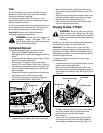
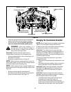

17
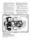
Parking Brake Adjustment
WARNING: Never attempt to adjust the
brakes while the engine is running. Always
disengage PTO, stop engine and remove key
to prevent unintended starting.
If the tractor does not come to a complete stop when
the brake pedal is completely depressed, or if the
tractor’s rear wheels can roll with the parking brake
applied, the brake is in need of adjustment. The brake
disc can be found on the right side of the transmission
in the rear of the tractor. Adjust if necessary as
follows.
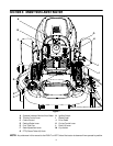
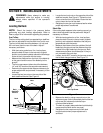
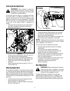
• Looking at the transmission from the right side of
the tractor, locate the compression spring and
brake disc. See Figure 11.
Figure 11
• Carefully remove the cotter pin from the crown nut
on the right side of the brake assembly.
• Using a feeler gauge, check the gap between the
brake disc and the brake puck. Proper gap is .011".
• Tighten the crown nut until the proper gap is
achieved.
• Insert a replacement cotter pin (part # 714-0111)
into the crown nut.
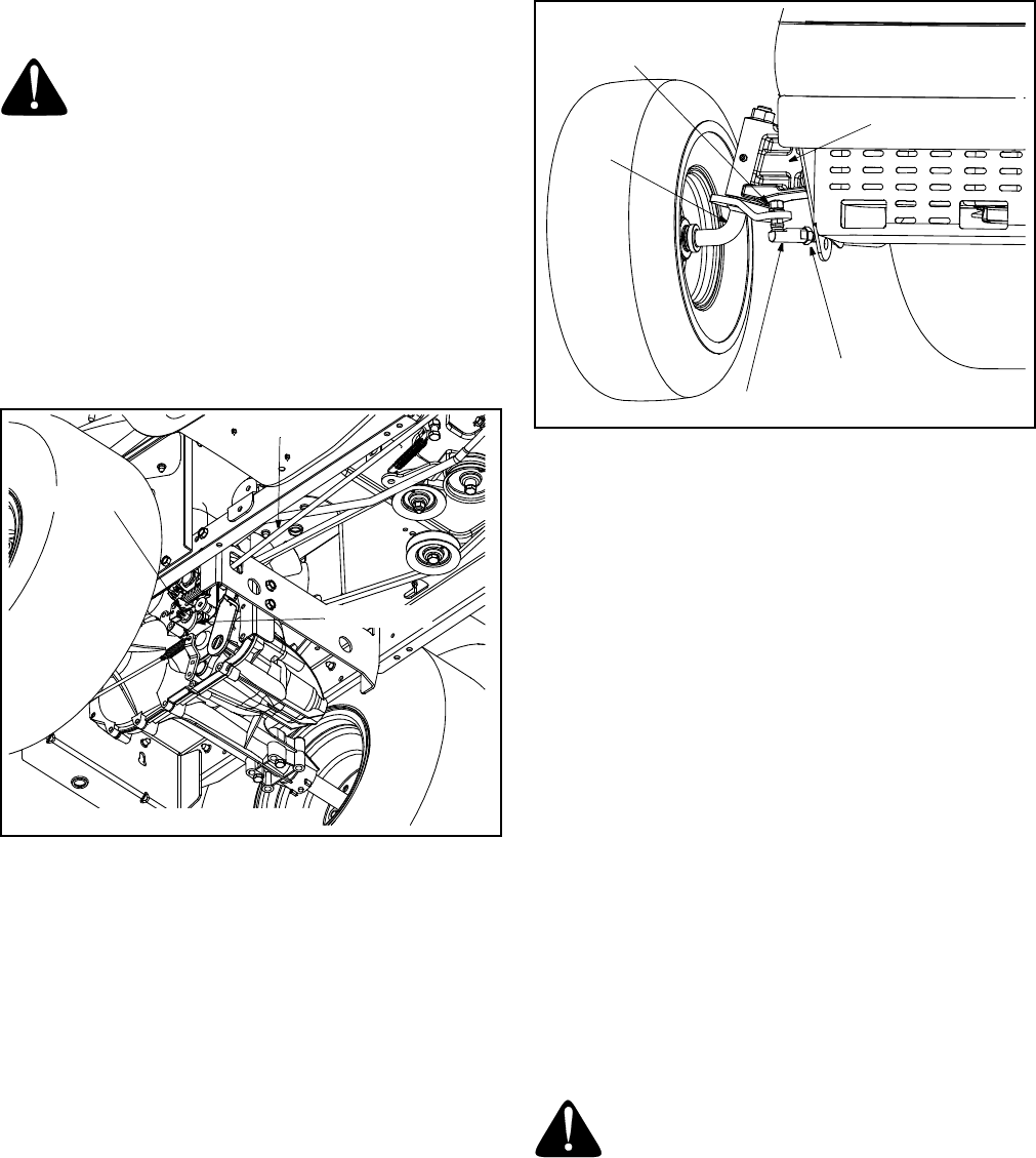
Steering Adjustment
If the tractor turns tighter in one direction than the other,
or if the ball joints are being replaced due to damage or
wear, the steering drag links may need to be adjusted.
Adjust the drag links so that equal lengths are threaded
into the ball joint on the left side and the ball joint on the
right side:
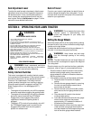
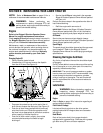
• Loosen the jam nut found on the drag link at the
rear of the ball joint. See Figure 12.
• Remove the hex nut and lock washer on the top of
ball joint. See Figure 12.
Figure 12
• Thread the ball joint toward the jam nut to shorten
the drag link. Thread the ball joint away from the
jam nut to lengthen the drag link.
• Replace hex nut and lock washer and retighten the
jam nut after proper adjustment is achieved.
NOTE: Threading the ball joints too far onto the drag
links will cause the front tires to "toe-in" too far. Proper
toe-in is between 1/16" and 5/16".
Front tire toe-in can be measured as follows:
• Place the steering wheel in position for straight
ahead travel.
• In front of the axle, measure the distance
horizontally from the inside of the left rim to the
inside of the right rim. Note the distance.
• Behind the axle, measure the distance horizontally
from the inside of the left rim to the inside of the
right rim. Note the distance.
• The measurement taken in front of the axle should
be between 1/16" and 5/16" less than the
measurement taken behind the axle.
• Adjust if necessary.
Seat Adjustment
WARNING: Before operating this machine,
make sure the seat is engaged in the seat
stop, stand behind the machine and pull back
on seat until fully engaged into stop.
To adjust the position of the seat, move the seat
adjustment lever (Refer to Figure 1 on Page 9) to the
left and slide the seat forward or rearward. Make sure
seat is locked into position before operating the tractor.
Brake Rod
Crown Nut
Brake Disc
NOTE: View shown from beneath tractor.
Ball Joint
Axle
Pivot Bar
Hex Nut and
Jam Nut
Lock Washer