


Section 6— Maintenance & adjuStMentS
26
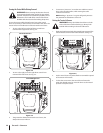
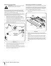
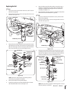
Adjusting the Rear Deck Rollers (If so equipped)
The rear deck rollers can be set in either the low or high position.
The position on the rear deck rollers is generally not changed. In
the low position the rollers will roll the grass. In the high position,
the rollers are in a storage position and do little or no rolling of
the grass. Change the roller position as follows:
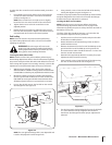
See Figure 6-7.
Cotter
Pin
High
Position
Low Position
Right Rear
Roller Bracket
J-Hook
Roller
High
Position
Low
Position
Figure 6-7
2.
shaft is fully withdrawn from the left rear roller bracket. See
Figure 6-7.
4.
the desired position and secure with the cotter pin once in
place.
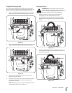
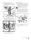
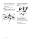
Adjusting the Front Gauge Wheels
WARNING!: Keep hands and feet away from the
discharge opening of the cutting deck.
The front gauge wheels on the mower deck are an anti-scalp
feature, and should not ride on the ground. The front gauge
wheels should be approximately ⁄⁄
the deck is set in the desired height setting.
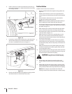
Using the lift handle, set the deck in the desired height setting,
then check the gauge wheel distance from the ground below. If
necessary adjust the front gauge wheels as follows:
Visually check the distance between the front gauge
wheels and the ground. If the gauge wheels are near or
touching the ground, they should be raised. If more than
⁄
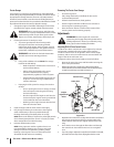
2. Remove the lock nut securing one of the front gauge wheel
shoulder screws to the deck. Remove the gauge wheel and
shoulder screw. See Figure 6-6.
Lock
Nut
Front Gauge
Wheel
Shoulder
Screw
Gauge Wheel
Bracket
Index Holes
Figure 6-6
Insert the shoulder screw into the one of four index holes
in the front gauge wheel bracket that will give the gauge
wheel a ⁄⁄
4. Note the index hole of the just adjusted wheel, and adjust
the other front gauge wheel into the respective index hole
of the other front gauge wheel bracket.