


3
Figure 6
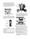
• Slide the lock washer (Ref.7) onto the special
screw, then thread the hex jam nut (Ref.4) onto the
screw. Refer to Figure 6.
NOTE: Because of limited space between the ped-
al shaft plate and frame, it may be easier to install
the hex jam nut from the underside of the tractor.
• Fully tighten the hex jam nut onto the special
screw. Then from beneath the right running board
carefully retighten the hex lock nut to reposition the
pedal shaft. Refer to Figure 5.
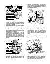
• Hook the bent tab of the magnet (Ref. 2) into the
square hole of the pedal shaft plate and pivot the
magnet onto the special screw (See Figure 7).
Push the magnet onto the screw so that the bent
tab is behind the plate and retains the magnet on
the screw.
Figure 7
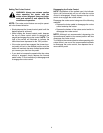
• Remove the two hex tapp screws securing the
right side of the tractor drive shaft shield to the
frame. Refer to Figure 8.
• Insert the cruise latch bracket (Ref. 3) down
through the opening in the fender/running board so
that its large plate area is against the left side of
the magnet. See Figure 8.
Figure 8
• Pivot the rear of the cruise latch bracket downward
so that the bracket mounting holes align with the
holes of the drive shaft shield. Refer to Figure 8.
• While holding the cruise latch bracket tightly
against the magnet, secure the bracket with the
two hex tapp screws removed earlier. Refer to Fig-
ure 8.
• Locate the unused two wire connector of the main
wire harness along the right side of the frame (See
Figure 9). Plug the two wires from the magnet into
the wire harness connector.
Figure 9
• Use the cable tie (Ref.5) to secure the wire har-
ness lead and magnet wires to the main harness,
away from the drive shaft. Refer to Figure 9.
Special Screw
Lock Washer
Tractor
Frame
Hex
Jam
Nut
Pedal Shaft Plate
Spring
Magnet
Square
Hole
Bent Tab
Hook tab &
pivot onto
screw
Hex Tapp
Cruise
Magnet
Latch
Bracket
Screw
Drive Shaft Shield
Wire Harness
Connector
Main Harness
Drive Shaft