


12
• Retighten the jam nut to secure the cable when
correct adjustment is reached.
• Reassemble the frame cover.
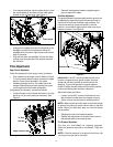
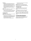
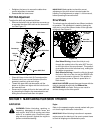
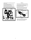
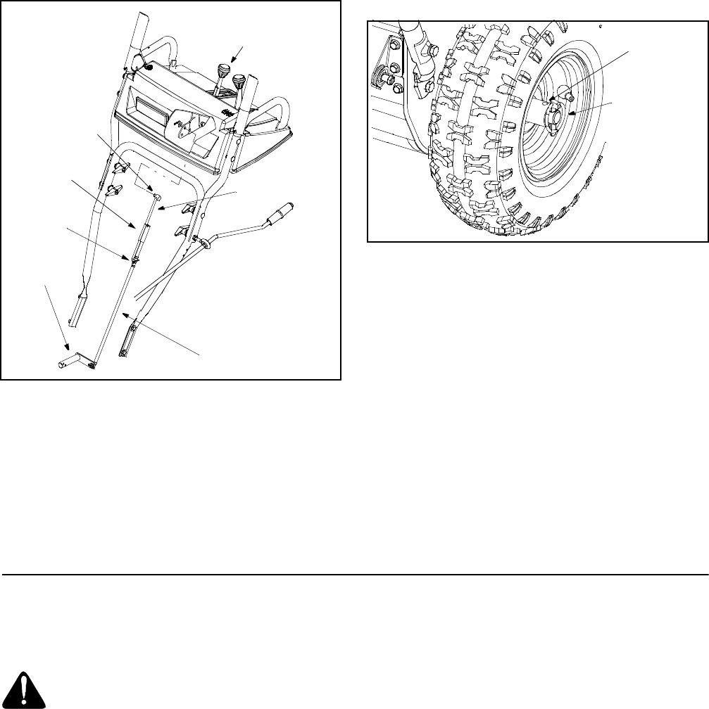
Shift Rod Adjustment
To adjust the shift rod, proceed as follows.
• Remove the hairpin clip and slide the connector up
to separate the upper shift rod from the lower shift
rod. See Figure 11.
Figure 11
• Place shift lever in the sixth (6) Forward position.
• Rotate the shift arm counterclockwise (from the
operator’s position) as far as it will go.
• Thread the upper shift rod downward until the
elbow on its lower end aligns with the hole found in
the lower shift rod.
• Reconnect the upper shift rod to the lower shift rod
by reinserting the hairpin clip removed earlier and
sliding the connector back down into place.
IMPORTANT: Make certain to check for correct
adjustment of the shift rod as instructed under the
heading Final Adjustments on page 11 of this manual,
before operating the snow thrower.
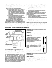
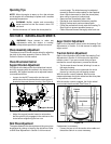
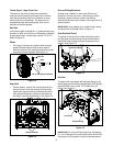
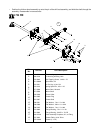
Drive Wheels
The wheels may be adjusted for two different methods
of operation. The adjustment is made by placing the
click pins in one of two different holes on the right side
of the unit. See Figure 12.
Figure 12
One Wheel Driving—Insert the click pin only
through the outside hole of the axle (NOT the rim)
on the right side of the snow thrower. This position
gives power drive to the left wheel only, making the
unit easier to maneuver.
Both Wheels Driving—Insert the click pin through
the hole in the hub of the rim and the INSIDE hole
on the snow thrower’s right axle. This position is
good for heavy snow as there is power drive in
both wheels.
IMPORTANT: NEVER operate the snow thrower with the
click pin inserted through both the RIM and the
OUTSIDE HOLE in the axle. Doing so can result in
serious damage to the drive system.
SECTION 7: MAINTAINING YOUR SNOW THROWER
Lubrication
WARNING: Before lubricating, repairing, or
inspecting, disengage all clutch levers and
stop engine. Wait until all moving parts have
come to a complete stop. Disconnect spark
plug wire and ground it against the engine to
prevent unintended starting.
Engine
Refer to the separate engine manual packed with your
unit for all engine lubrication instructions.
IMPORTANT: When following instructions in separate
engine manual for draining oil, be sure to protect frame
to avoid oil dripping onto transmission parts.
Shift Lever
Ferrule
Shift Arm
Hairpin
Clip
Lower Shift Rod
Upper Shift Rod
Connector
Inside Hole
in Axle
Click Pin
in Outside Hole