


23
hoses. Make certain there are no kinks or
twists in any hose.
2.
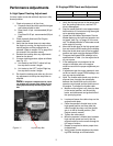
Hydraulic Oil Tank and Filter:
Note: Change the hydraulic oil and the oil
filter element after the first 50 hours of opera
-
tion and every 500 hours thereafter.
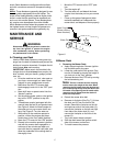
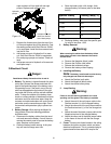
To drain the hydraulic oil tank, place a 2 gallon drain
pan under the drain plug on the bottom of the
hydraulic oil tank. Remove the drain plug, drain the
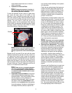
tank, then replace the plug. Remove the three screws
from the top of the oil filter and take out the oil filter
element. You don’t have to drain the rest of the
hydraulic system. Put the replacement filter element
in the oil filter and lubricate the sealing surface. Install
the three screws in the top of the oil filter to secure
the oil filter element. (See photo below)
Note: Always wipe off the hydraulic tank fill
cap and the area around it before removing
the cap to prevent dirt from contaminating the
oil.
Remove the fill cap and fill the tank with the same
15W40 oil selected for the filter until the oil level is a
1/4” below the oil tank fill neck. Leave this air space
for expansion. Start the engine and let it run at idle for
about five minutes. Check the filter for leaks. Idling the
engine and the pumps in this way will purge any air
from the system. Shut off the engine and recheck the
oil level in the tank. Top-off if necessary until the oil
level is a 1/4” below the oil tank fill neck.
Note: After unit is up to operating tempera-
ture, turn off engine and re-check hydraulic
oil. If oil appears foamy or contains excessive
air bubbles, DO NOT OPERATE UNIT. Contact
service technician.
3.
Hydrostatic Pumps and Motors:
The pumps
are the hardest-working components in the
hydraulic system. They are in operation all the
time the engine is running. Because of
extremely close tolerances, wear is an impor
-
tant factor in their life.
Contaminants
in the
hydraulic oil and
cavitation
does the greatest
harm to the pumps. Cavitation is a blockage in
the supply lines that produces a partial vac
-
uum causing violent bubbling in the hydraulic
oil in the pump.
Check the two suction hoses (the hoses con-
nected to the filter) daily before starting the
engine. Look for a flattened condition or any
leaks and repair or replace as necessary. A
flattened or leakng suction hose will permit
cavitation to develop which can destroy the
pumps in a short time.
Contaminants or foreign matter in the oil will
also damage the pumps . To prevent this, use
a filter that captures particles as small as 25
microns or 25 millionths of a meter in diame
-
ter. You can help in the battle against dirt by
being very careful when you remove or repair
a component in the hydraulic system. Thor
-
oughly clean off any component before you
work on it. Plug the ends of any hose or line
you remove with a rubber or plastic plug. Use
plastic caps to seal off the ends of hydraulic
fittings. Place any component you remove in a
clean plastic bag so it can’t pick up dust or
dirt. Clean your hands frequently when work
-
ing on the hydraulic components.
Note: The pumps are not owner-repairable.
If a pump fails, contact your Cub Cadet Com
-
mercial dealer. Do not disassemble the pump.
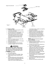
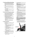
4.
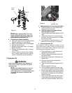
Steering Lever Adjustments:
The steering
lever controls on this Zero Turn Mower (ZTM)
incorporate a patented interlock mechanism
that secures them in their Neutral position
whenever the Park Brake lever is applied.
Additionally, the lap bars can be opened in
any position - Neutral, when traveling For
-
ward, when traveling in Reverse, or when exe-
cuting a zero-turn maneuvar. The lap bars
also incorporate a Return-To-Neutral (RTN)
feature with hydraulic dampers to provide
smooth, non-jerkey, control motion while
affording an automatic hydrostatic braking
means.
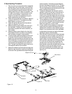
Whenever the Park Brake lever is moved rear-
ward to the Park Brake engaged position, a
cable mechanism, connected to each drum
brake on the hydrostatic wheel motors,
applies force to each brake lever so that each
wheel brake mechanism can prevent brake
drum and wheel rotation. At the same time, a
second cable and linkage mechanism is acti
-
vated to secure both lap bars in their Neutral
positions and to activate the Park Brake
switch. Both lap bars must be in their Neutral
positions for the neutral lock linkage to func
-
tion - the spring-loaded linkage will force rods
in through aligning holes in each lap bar
Screw
Screw