


14
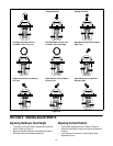
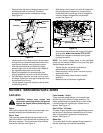
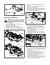
• Remove bolts that secure linkage to upper control
handles and lower control arms. The shock
absorbers should remain connected to linkage.
See Figure 12.
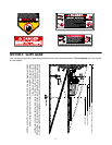
Figure 12
• Insert quarter inch by seven inch pin or equivalent
through the top and bottom alignment holes of the
control arms to secure arms at positive neutral.
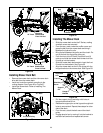
• With the shock absorber still bolted to linkage,
loosen the jam nuts at both ends of the linkage so
the alignaball adjustment can be made.
• Adjust the alignaball until retaining bolts slips
through alignaball and hole in arm with little effort.
• Re-install bolts, washers, and nuts in all four ends
of linkage. Tighten jam nuts against alignaball ends
to keep ends from turning.
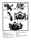
• Lift rear wheels off ground using floor jack or other
suitable lifting device.
• With quarter inch by seven inch pins still installed in
the top and bottom linkage arms, loosen the jam
nuts at both the front and rear ends of linkage that
runs from bottom linkage arms to hydrostatic
pumps. See Figure 13.
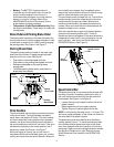
Figure 13
• Set parking brake and start the engine (set throttle
at full speed). Make sure that the PTO is OFF.
• Rotate rods (lengthen or shorten) to bring each
hydrostat to neutral.
NOTE: The control linkage going to the hydrostatic
pump has left-handed threads at the pump and right-
handed threads at the tower.
• Tighten the jam nuts earlier loosened and
reassembled the safety switches.
• Remove quarter inch by seven inch pins from top
and bottom holes.
• Reassemble body panels and drive handle
assembly.
• Make sure that all hardware is tightened.
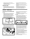
SECTION 6: MAINTAINING YOUR Z-SERIES
Lubrication
WARNING: Always stop engine and
disconnect spark plug wire(s) and ground
against the engine before performing any
maintenance.
Engine
Lubricate the engine with motor oil as instructed in the
separate engine manual packed with your unit.
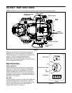
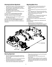
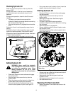
Control Tower
There are two grease fittings that are located on the
right side of tower. Lubricate both with a grease gun at
least once a season. The control tower cover must be
removed to lubricate. See Figure 14.
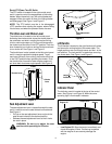
Caster Assembly / Wheels
There are three grease fittings, one on each wheel
spindle and one in middle of caster assembly. The
caster wheels have one grease fitting on each wheel.
Lubricate these with a grease gun at least once a
season. See Figure 14.
Deck Lift Pivot / Lift Handle
The deck lift pivot assembly has grease fittings on each
end and the lift handle has a grease fitting on its lower
side. Lubricate with a grease gun at least once a
season. See Figure 14.
Mower Deck
The mower deck may have grease fittings located on
the idler assembly or the spindle assemblies.
Hex Bolt
Alignment
Holes
Alignment
Holes
Jam Nuts
Jam Nuts
Alignaball
Alignaball
Hex Bolt
Jam Nuts
Spherical Rods