25
f. Repeat as required to obtain proper throt-
tle adjustment.
g. Verify proper throttle adjustment by check-
ing RPM readings as outlined above.
C. Deck Corner Ball Wheel Roller Settings
1. Matching the set heights of the ball rollers on
the four corners of the mower deck to the
desired cut height will prevent edge scalping
and minimize any side-to-side variance in cut
height.
2. There are three height adjustment holes in
the bracket that mount the ball rollers to the
deck.
a. Use the top set of holes for cut heights of 2
inches or lower.
b. Use the middle set of holes for a 2-1/2 - 3-1/2
inch cut height.
c. Use the bottom set of holes for cut heights of
4 inches or higher.
D. Deck Center Anti-Scalp Roller Settings
1. The front and rear rollers help prevent the
scalping of high spots and uneven terrain
across the center section of the deck.
2. The rollers on the front of the deck are fixed at
the factory and can not be adjusted.
3. The rollers on the rear of the deck can be
adjusted downward one inch.
a. Lowering the roller will increase the strip-
ing effect left behind the mower.
b. This positioning of the rear roller will also
help to filter the mulched grass clippings
into the turf.
c. Roller should not be lowered if the cut
height is set at 2-1/2 inches or lower.
E. Lap Bar Adjustment
1. Proper lap bar and seat adjustment will result
in the following:
a. In the neutral position with hands on the
lap bars,
1. Operator’s upper arms should be relaxed
and approximately vertical.
2. Operator’s forearms should be approxi-
mately vertical.
b. In the full forward position,
1. Operator’s back should stay in contact
with the seat back.
2. Lap bars should not contact operator’s
legs.
c. In the full reverse position,
1. Lap bars should not contact the opera-
tor’s legs or torso.
2. Set the seat to the preferred operating position.
a. Adjustment lever is located under the front
edge of the seat.
b. The seat has five inches of front-to-rear
adjustment available.
3. Check factory settings of lap bars for the con-
ditions listed above.
Note:
If lap bar adjustments are required,
height adjustments should be made prior to
angular adjustments.
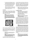
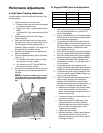
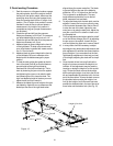
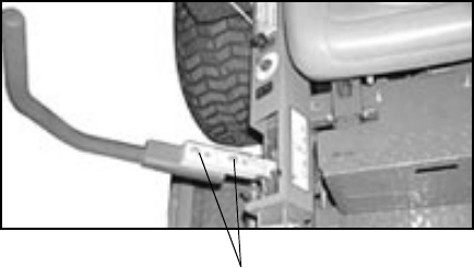
4. To adjust the height of the lap bars,
a. Remove the nuts from the lap bar mounting
bolts (see Fig. 11).
b. Remove the bolts and lap bar and repostion
to the seconc set of holes in the mounting
block.
c. Replace the bolts and nuts and tighten to
28-34 ft-lbs.
1. If angular adjustments are also required,
nuts can be tightened until snug at this
point.
d. The same adjustments should be made to
both sides of the mower.
5. To adjust the front-to-rear angle of the lap bars,
a. Loosen the nuts on the lap bar mounting
bolts, leaving the bottom one fairly snug.
b. The top hole is slotted, allowing the lap bar
to pivot on the bottom bolt.
c. Move lap bar to the desired angle and
tighten the nuts to 28-34 ft-lbs.
Note:
In the neutral position, the handles of
the lap bars should be aligned with approxi-
mately a one inch gap between the tips. Adjus-
the gap by adding shim washers to the top
mounting bolt between the lap bar and the
mounting block.
d. Check the results of any adjustments to
the conditions described in section a,
above. Repeat any adjustment procedures
as required until all conditions are met.
Figure. 11
Lap Bar Mounting Bolt and Nuts


