


20
d. Loosen jam nuts on both ends of rod con-
nectors. See Control Assembly in the Illus-
trated Parts Book (ONLY if mower creeps.)
e. Start unit and push throttle all the way on.
f. If unit creeps forward rotate rear rod con-
nectors counter-clockwise. And if unit
creeps in reverse, rotate clockwise.
Adjust the appropriate rod connector. The
left rod for the left side of the mower and
the right rod for the right side of mower.
Afterward, retighten jam nuts.
E. Brakes
While the mower is in motion, all braking is performed
dynamically through the hydraulic pumps and traction
motors, controlled by the two steering levers. When the
mower is parked with the engine shut off, the hydraulic
system locks the traction wheels.
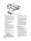
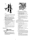
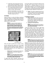
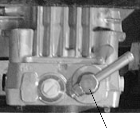
Note:
To move the mower forward or in
reverse by pushing, you must release the
dynamic braking. Locate the valves on the
pump. Turn valves counter-clockwise one
quarter turn to push the unit. After pushing
the mower to the desired location, return both
valves to the operating position (See photo
below)
.
When the mower is parked with the engine running
and the steering levers opened out in the neutral
position, the parking brakes should be applied. The
parking brakes are drum-type brakes mounted on
each traction wheel.They are both engaged by the
same operating lever.
1.
Adjustments:
The parking brake handle is an
overcenter lever that should engage with
moderate force.
Note:
To increase parking brake capacity
tighten the brake rods going back to the brake
arms equally. Tighten rods one full turn and
check parking capacity. Repeat Step.
To adjust either brake individually, disconnect the
brake rod from the brake arm by removing the cotter
pin from the clevis pin and pulling the clevis pin from
the brake clevis. Loosen the hex nut and turn the
brake clevis in a clockwise direction one full turn
looking down the brake rod. This will tighten the brake
about .040 inch. Tighten the hex nut and reassemble
the brake clevis to the brake shaft assembly. Normally,
both brakes should be adjusted and equal amount.
2.
Repair:
The mower is equipped with internal
wet drum brakes and will not normally require
maintenance. If they are not working properly,
please contact your service center.
F. Hydraulic System
1.
Hoses:
Check the hoses from the hydraulic
oil tank to the oil filter to the hydraulic lines
daily for leaks or abrasion and replace any
damaged hoses. Make certain there are no
kinks or twists in any hose.
2.
Hydraulic Oil Tank and Filter:
Note:
Change the hydraulic oil and the oil
filter after the first 50 hours of operation and
every 500 hours thereafter.
To drain the hydraulic oil tank, place a 2 gallon drain
pan under the drain plug on the bottom of the
hydraulic oil tank. Remove the drain plug, drain the
tank, then replace the plug. Place the drain pan under
the filter and remove the filter by unscrewing in a
counterclockwise direction. The filter will be full of oil,
so empty it into the drain pan. You don’t have to drain
the rest of the hydraulic system. Fill the replacement
filter with a good grade of 20W-50 oil and lubricate the
sealing surface. Screw the filter onto the filter base
until it seats and then another one-half turn to seal.
Note:
Always wipe off the hydraulic tank fill
cap and the area around it before removing the
cap to prevent dirt from contaminating the oil.
Remove the fill cap and fill the tank with the same
20W-50 oil selected for the filter until the oil level is up
to the level of the second hole in the fill tube. Leave
this air space for expansion. Start the engine and let it
run at idle for about five minutes. Check the filter for
leaks. Idling the engine and the pumps in this way will
purge any air from the system. Shut off the engine
and recheck the oil level in the tank. Top-off if
necessary until the oil level is up to the second hole in
the fill tube.
Note:
After unit is up to operating tempera-
ture, turn off engine and re-check hydraulic
oil. If oil appears foamy or contains excessive
air bubbles, DO NOT OPERATE UNIT. Contact
service technician.
Hydro Release Valve