


41
Figure 50
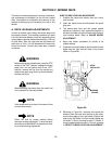
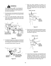
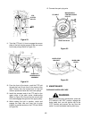
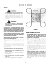
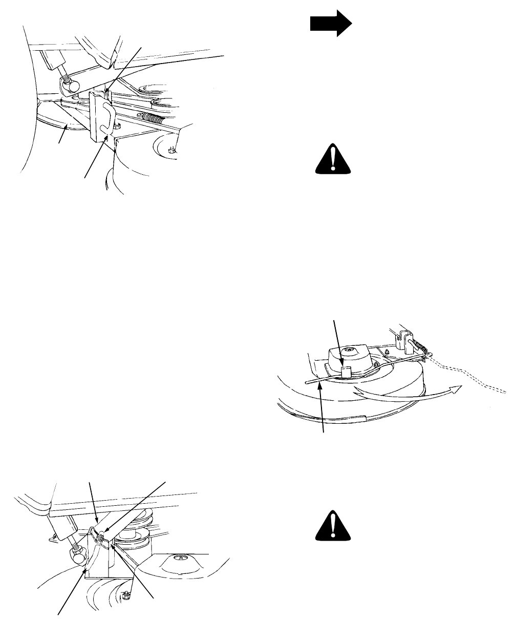
7. Carefully guide the tractor implement lift links (left
and right) into the rear deck bracket slots (left and
right) as the tractor implement lift handle is
lowered to its lowest setting (Refer to Figure 51).
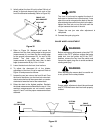
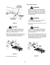
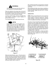
8. Pull both deck support pins outward and rotate
rearward to disengage the outer surface ot the rear
deck brackets. Release the pins, making certain
each deck support pin passes through the inner
hole of the rear deck bracket. The spring tension
will push the pins inward and, if aligned, through
the hole in each implement lift link (Refer to Figure
51).
Figure 51
NOTE
It may be necessary to lift each side of the deck
and maneuver it slightly to align the support
pins with the holes of the lift links. Make certain
the support pins are fully extended through the
lift links to prevent the mower deck from
disengaging the lift links while mowing.
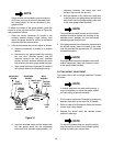
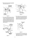
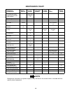
WARNING
The deck idler arm lever is spring loaded.
Release it slowly.
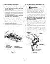
9. Disengage the deck idler arm lever from its stop
bracket and release the spring tension by rotating
the lever out and rearward (Refer to Figure 52).
Figure 52
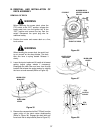
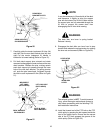
WARNING
The exhaust system is HOT. To avoid personal
injury, allow the engine and exhaust system to
cool before proceeding with the following PTO
belt installation instructions.
10. Install the forward end of the PTO belt on the PTO
clutch pulley by passing the belt upward inside the
front of the tractor frame. Ensure that the narrow
side of the PTO belt engages the groove of the
clutch pulley (Refer to Figure 53).
REAR DECK
BRACKET SLOTS
DECK SUPPORT
PIN DISENGAGED
DECK
IMPLEMENT
LIFT LINKS
(BOTH SIDES)
LIFT LINK HOLE
(BOTH SIDES)
SLOT IN REAR
DECK BRACKET
DECK SUPPORT
PIN ENGAGED
IDLER ARM
LEVER
LEVER STOP
BRACKET