


24
SECTION 8: SERVICE
Head Lamp
WARNING:
If the engine has been recently
run, the engine, muffler and surrounding
metal surfaces will be hot and can cause
burns to the skin. Allow the tractor to cool and
use caution when changing the lamp bulbs.
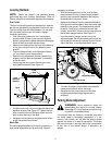
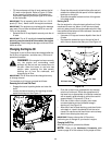
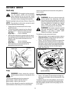
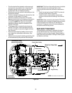
Replace headlight bulbs as follows (Refer to Figure 23):
NOTE:
Pay attention to which wire connects to each
lamp terminal before disconnecting.
• Unplug the wire harness leads from the lamp
socket terminals.
• To remove the bulb & socket from the reflector
housing, rotate the socket as follows to unlock:
Left lamp — 1/4 turn counterclockwise.
Right lamp — 1/4 turn clockwise.
• With the terminals pointing upward, align the tab of
the replacement bulb & socket with the notch of the
reflector. Push then socket inward and turn as
follows to lock:
Left lamp — 1/4 turn clockwise.
Right lamp — 1/4 turn counterclockwise.
• Re-connect the wire harness leads to the
appropriate socket terminals.
Figure 23
Tires
WARNING:
Never exceed the maximum
inflation pressure shown on the sidewall of the
tire.
The recommended operating tire pressure is:
approximately 10 psi for the rear tires and
approximately 14 psi for the front tires.
Refer to the tire sidewall for exact tire manufacturer’s
recommended or maximum psi. Do not overinflate.
Uneven tire pressure could cause the cutting deck to
mow unevenly.
Cutting Blades
WARNING:
Be sure to shut the engine off,
remove ignition key, disconnect the spark
plug wire(s) and ground against the engine to
prevent unintended starting before removing
the cutting blade(s) for sharpening or replace-
ment. Protect your hands by using heavy
gloves or a rag to grasp the cutting blade.
WARNING:
Periodically inspect the spindle
bolts and housings for cracks or damage,
especially if you strike a foreign object.
Replace immediately if damaged
.
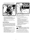
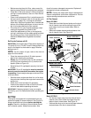
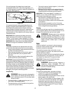
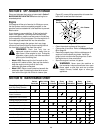
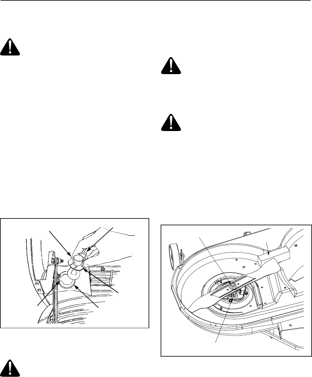
The blades may be removed as follows.
• Remove the deck from beneath the tractor, (refer to
Cutting Deck Removal on page 25) then gently flip the
deck over to expose its underside.
• Use a 1-1/8 inch wrench to hold the hex head of the
spindle bolt when loosening the hex nut securing
the blade. A block of wood may be placed between
the deck housing and the cutting edge of the blade
to assist in removal of the hex nut securing the
blade. See Figure 24.
Figure 24
• Use a 1-1/8" wrench to remove the hex flange nut
that secures the blade to the spindle assembly. See
Figure 24.
To properly sharpen the cutting blades, remove equal
amounts of metal from both ends of the blades along
the cutting edges, parallel to the trailing edge, at a 25°
to 30° angle.
Reflector
Socket Tab
Terminal
Socket
Reflector
Housing
Notch
Spindle Assembly
Hex Flange Nut
Wood Block