


11
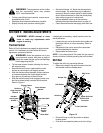
WARNING: The temperature of the muffler
and the surrounding areas may exceed
150
°
F. Avoid these areas.
• For the most efficient snow removal, remove snow
immediately after it falls.
• Discharge snow downwind whenever possible.
• Slightly overlap each previous cleaning path.
• Set the skid shoes 1/4" below the shave plate for
normal usage. The skid shoes may be adjusted
upward (to lower the shave plate) for hard-packed
snow. Adjust downward (to raise the shave plate)
when using on gravel or crushed rock.
• Prevent possible freeze-up of the starter by
following the steps described earlier on page 10.
• Clean the snow thrower thoroughly after each use.
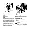
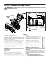
SECTION 5: MAKING ADJUSTMENTS
WARNING: NEVER attempt to clean
chute or make any adjustments while
engine is running.
Traction Control
Refer to Final Adjustments on page 6 to adjust traction
control. If it is necessary to check further for correct
adjustment, proceed as follows:
WARNING: Drain the gasoline out of your
snow thrower’s engine, and place a piece of
plastic film under the gas cap to avoid spillage
before beginning the job.
• Tip the snow thrower forward, allowing it to rest on
the auger housing.
• Remove the frame cover underneath the snow
thrower by removing six self-tapping screws.
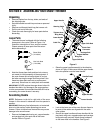
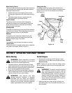
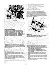
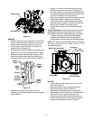
• With the traction control released, make sure there
is clearance between the friction wheel and the
drive plate in all positions of the shift lever.
• With the traction control lever engaged, make sure
the friction wheel solidly contacts the drive plate.
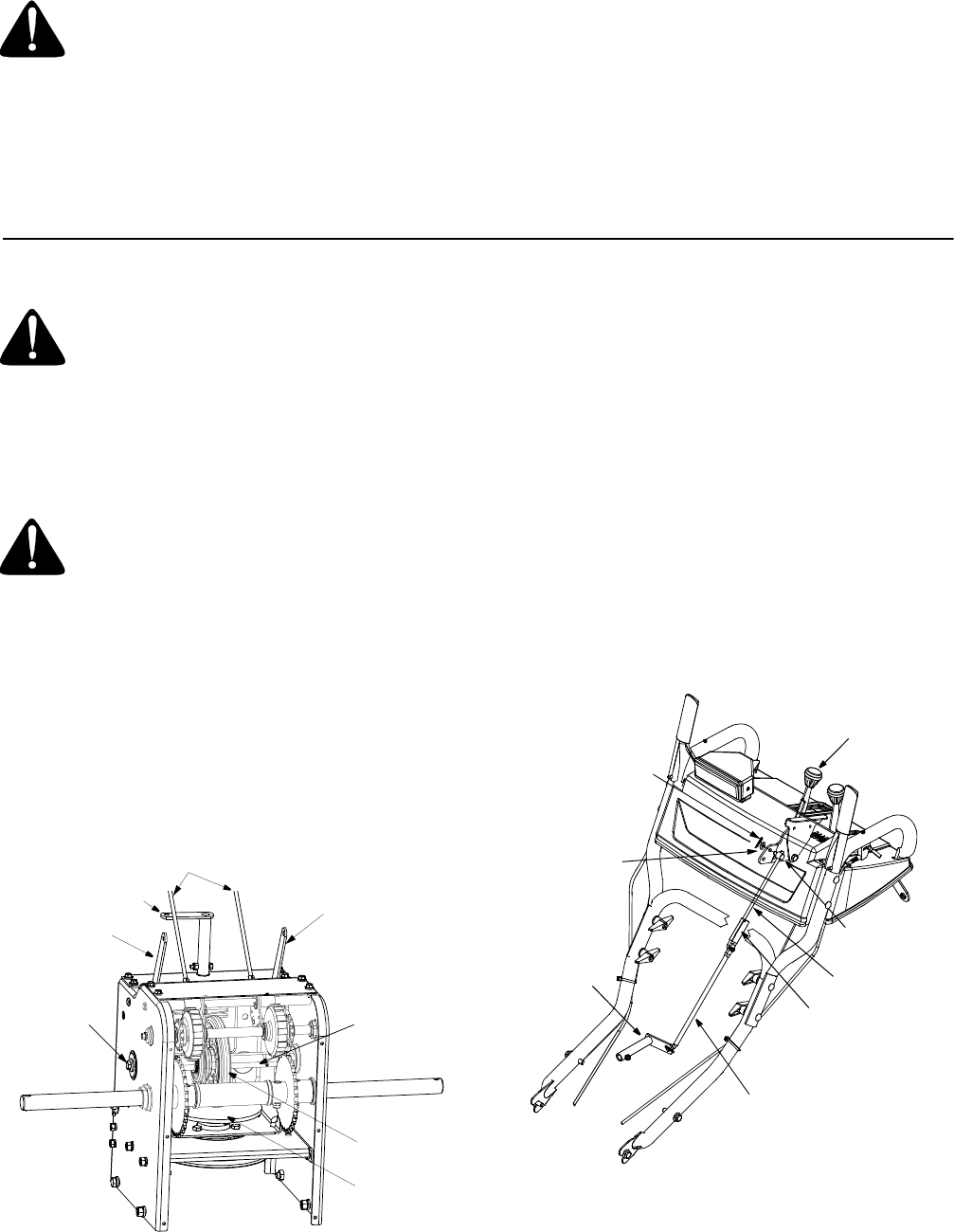
Refer to Figure 11.
Figure 11
If adjustment is necessary, adjust traction control as
instructed below:
• Loosen the jam nut on the traction drive cable and
thread the cable in or out as necessary. Refer to
Figure 7.
• Retighten the jam nut to secure the cable when
correct adjustment is reached.
• Reassemble the frame cover.
NOTE: If you placed plastic film under the gas cap, be
certain to remove it before operating the snow thrower.
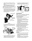
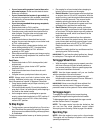
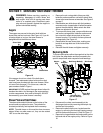
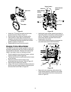
Shift Rod
To adjust the shift rod, proceed as follows:
• Remove the hairpin clip and flat washer from the
shift handle under the handle panel.
Figure 12
• Place shift lever in sixth (6) position or fastest
forward speed.
• Push shift arm assembly down as far as it will go.
Trigger Cables
Shift Arm
Drive Actuator
Bracket
Auger Actuator
Bracket
Hex Nut
and Cupped
Washer
Friction
Hex Gear Shaft
Wheel
Drive Plate
Rubber
Shift Lever
Ferrule
Shift Arm
Lower Shift Rod
Clutch Rod
Upper Shift Rod
Connector
Hairpin Clip
Flat Washer