


TiRE CARE
,_,CAUTION: When mounting tires, un-
less beads are seated, overinflation can
cause an explosion.
o Maintain 20 pounds of tire pressure. If
tire pressures are not equal, tiller will
pull to one side.
. Keep tires free of gasoline or oil which
can damage rubber.
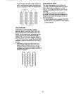
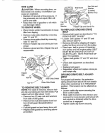
TO REMOVE WHEEL
o Place blocks under transmission to keep
tiller from tipping.
o Remove outer side shield by removing
nuts "A" and "B".
o Remove inner side shield by removing
nuts "C" and "D".
o Remove hairpin clip and clevis pin from
wheel.
o Remove wheel and tire.- Repair tire and
reassemble.
Clevis
t _
¢
Hairpin
Clip
Nut "B"
inner Side Shield
Hex Nut and
Be_tGuard Washer
(Located
ind Tire)
Cap Nut _ ___\_
and z%_j\ _ I
Washer Hairpin'Clip and Clevis Pin
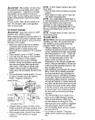
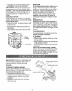
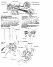
TO REPLACE GROUND DRIVE
BELT
= Remove belt guard as described in 'q'o
REMOVE BELT GUARD".
• Loosen belt guides "A" and "B" and
also remove stud "C"=
° Remove old belt by slipping off engine
pulley first then remove from the pulley.
• Place new belt in groove of transmis-
sion pulley and into engine pulley. BELT
MUST BE IN GROOVE ON TOP OF
IDLER PULLEY. NOTE POSITION OF
BELT TO GUIDES.
o Tighten belt guides '%" and "B" and stud
"C".
o Check belt adjustment as described
below°
o Replace belt guard.
° Reposition wheel and replace clevis pin
and hairpin clip.
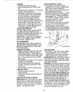
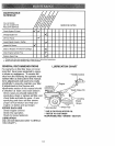
GROUND DRIVE BELT ADJUST-
MENT
For proper belt tension, the extension
-A,,/'f- Outer Side Shield spring should have about 5/8 inch stretch
Nut
when drive control bar is in "ENGAGED"
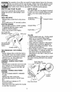
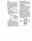
TO REMOVE BELT GUARD
NOTE: For ease of removal, remove hair-
pin clip and clevis pin from left wheel. Pull
wheel out from tiller about 1 inch.
° Remove two (2) cap nuts and washers
from side of belt guard.
° Remove hex nut and washer from bot-
tom of belt guard (located behind
wheel).
° Pull belt guard out and away from unit.
= Replace belt guard by reversing above
procedure.
position. This tension can be attained as
follows:
- Loosen cable clip screw securing the
drive control cable.
o Slide cable forward for less tension and
rearward for more tension until about 5/8
inch stretch is obtained while the drive
control bar is engaged.
o Tighten cable clip screw securely.
16