


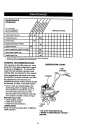

NARROW TILLING/CULTIVATING -
12-3/4" PATH
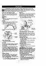
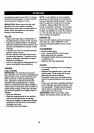
• Remove outer tines.
Inner Tines Only
NOTE: When reassembling outer tines,
be sure right tine assembly (marked "R")
and left tine assembly (marked =L') are
mounted to correct side of tine shaft.
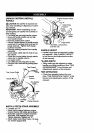
TINE OPERATION CHECK
ACAUTION: Disconnect spark plug wire
from spark plug to prevent starting while
checking tine operation.
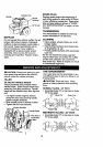
For proper tine operation, tine control lever
must be against control body and all slack
removed from inner wire of control cable
when control is in the =OFP (up) position.
If lever and cable are loose, loosen cable
clip at lower end of cable Pull up on cable
to remove slack, without extending spring
on end of cable, and retighten cable clip.
FINAL CHECK "OFF" POSITION
• With tine control "OFP (up), push down
on handle to raise tines off the ground.
• Slowly pull recoil starter handle while
observing tines. Tines should not
rotate.
• If tines rotate, inner wire of control cable
is too tight which is extending lower
spring and engaging tines. Loosen
cable clip and push down on cable only
enough to relieve spring tension.
Tighten cable clip.
• Recheck in "OFP position and adjust if
necessary.
FINAL CHECK "ON" POSITION
• With tine control "ON" (held down to
handle) push down on handle to raise
tines off the ground.
• Slowly pull recoil stader handle while
observing tines. Tines should rotate for-
ward.
• If tines do not rotate, inner wire of con-
trol cable is too loose. Loosen cable clip
and pull cable up to remove slack and
retighten clip.
• Recheck in "ON" position and adjust if
necessary.
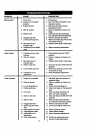
NOTE: If "ON" position check required
adjustment, recheck "OFF" position
adjustment to insure tines do not rotate
when control is "OFP (up).
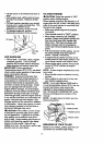
_;netr_
-.-"
Positiion line (.;ontrol _ \
"ON" Position " "
Cable Clip
Tir,e Control Cable
\
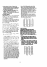
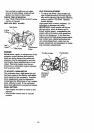
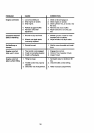
TO REMOVE BELT GUARD
• Remove screws from side of belt guard.
• Pull belt guard out and away from unit.
• Replace belt guard by reversing above
procedure. Be sure slot in bottom of belt
guard is under head of tine shield bolt
and all nuts are tightened securely.
Screw
J J ._ _ BeltGuard
I"'- \
Screw
TO REPLACE V-BELT
Replace V-belt if it has stretched consider-
ably or if it has cracks or frayed edges.
Belt guard must be removed to service
belt. See "TO REMOVE BELT GUARD"
in this section of manual.
BELT REMOVAL
• Remove V-belt from transmission pulley
first and then from engine pulley.
BELT REPLACEMENT
• Install new V-belt to engine pulley first
then to transmission pulley.
14