


40
OPERACIÓN
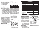
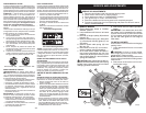
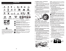
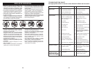
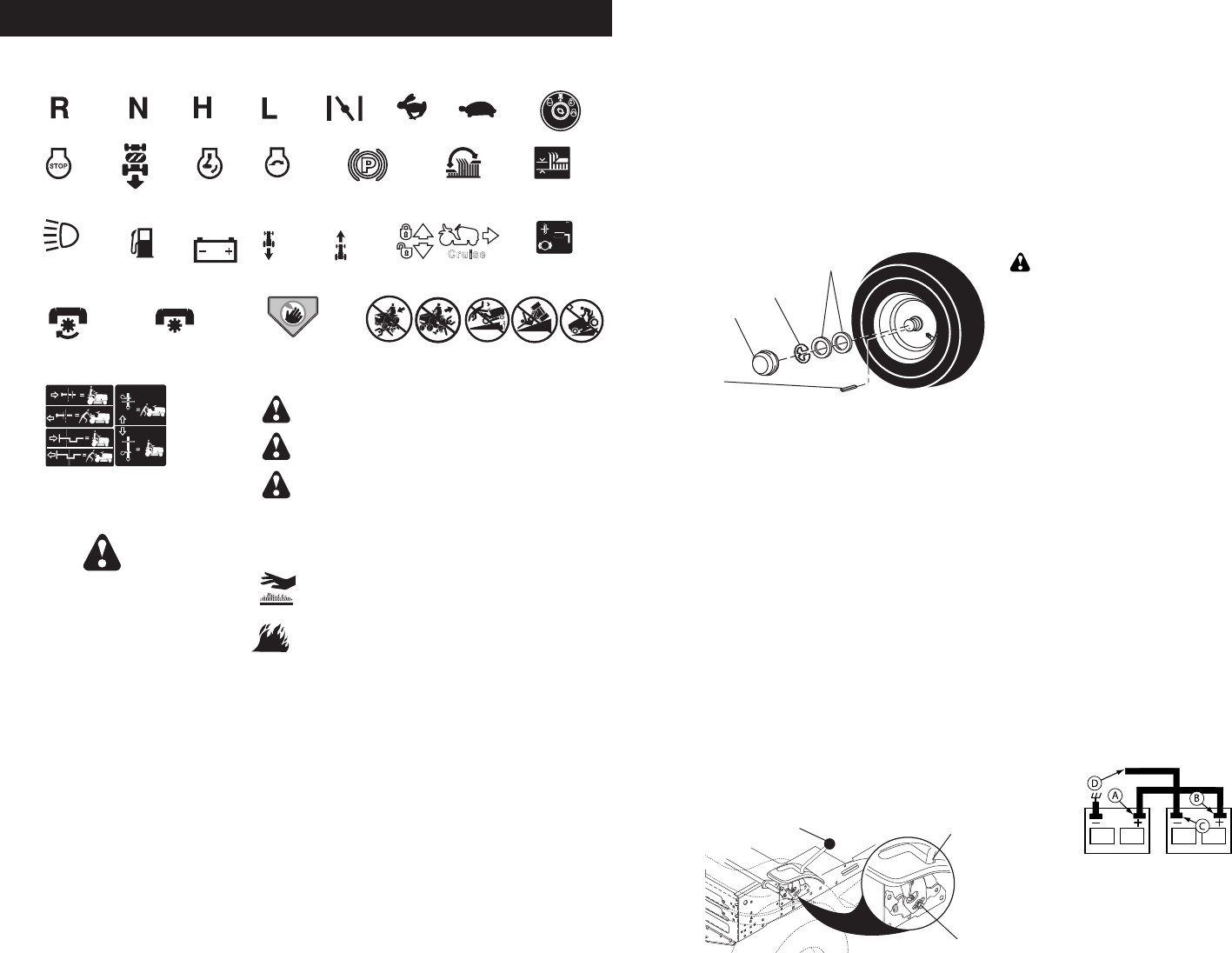
Estos símbolos pueden aparecer sobre su tractor o en la literatura proporcionada con el producto.
Aprenda y comprenda sus significados.
0%,)'2/ª'5!2$%ª,!3ª
-!./3ª9ª,/3ª0)%3ª,%*/3
25%$!ª,)"2%ª
3OLAMENTEªPARAªLOSª
MODELOSªAUTOMATICO
-!.4%.'!ª%,
!2%!ª$%30%*!$!
ª
-!.4%.'!ª%,
!2%!ª$%30%*!$!
ª
0%,)'2/3ª$%
0%.$)%.4%3
ª
ª
6EAªLAªSECCIØNªDEªLASªREGLASªDEªSEGURIDADª
"!4%2¶!
-!2#(!
!42«3
-!2#(!
(!#)!ª!$%,!.4%
2«0)$/
,%.4/
-/4/2
%.#%.$)$/
-/4/2
!0!'!$/
,5#%3
%.3%.$)$!3
#/-"534)",%
%342!.'5
,!#)».
!,452!ª$%ª,!ª
3%'!$/2!
-!2#(!ª!42«3
.%542/
!,4/
"!*/
!##%3/2)/ª$%,ª
%-"2!'5%
%.'!.#(!$/
&2%./ª$%
%34!#)/.!-)%.4/
!##%3/2)/ª$%,ª
%-"2!'5%
$%3%.'!.#(!$/
ª
-/4/2ª
%.ª-!2#(!
,%6!.4!-)%.4/
ª$%ª,!ª3%'!$/2!
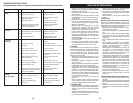
.OªSEGUIRªLASªSIGUIENTESªINSTRUCCIONESª
PUEDEªPROVOCARªHERIDASªOªMUERTEª,OSª
SÓMBOLOSªDEªAVISOªDEªSEGURIDADSEªUTILIZANª
PARAªIDENTIFICARªINFORMACIONESªDEªSEGURIDADª
RELATIVASªAªPELIGROSªQUEªPUEDENPROVOCARªLAª
MUERTEªHERIDASªGRAVESªYOªDA×OSªAªLAª
MÈQUINA
0%,)'2/ªINDICAªUNªPELIGROªQUEªSIªNOªSEªEVITAª
PROVOCAªMUERTEªOªLESIONESªGRAVESª
!$6%24%.#)!ªINDICAªUNªPELIGROªQUEªSIªNOªSEªEVITAª
PUEDEªPROVOCARªMUERTEªOªLESIONESªGRAVESª
02%#!5#)».ªINDICAªUNªPELIGROªQUEªSIªNOªSEªEVITAª
PUEDEªPROVOCARªLESIONESªLIGERASªOªMODERADASª
02%#!5#)».ªCUANDOªSEªUTILIZAªSINªELªSÓMBOLOªDEªAVISOª
INDICAªUNAªSITUACIØNªQUEªPUEDEªPROVOCARªDA×OSªALª
TRACTORªYOªALªMOTORª
&5%'/ªINDICAªUNªPELIGROªQUEªSIªNOªSEªEVITAªPUEDEª
PROVOCARªLAªMUERTEªLESIONESªGRAVESªYOªDANOSª
AªLAªMÈQUINAª
350%2&)#)%3ª#!,)%.4%3ªINDICAªUNªPELIGROªQUEª
SIªNOªSEªEVITAªPUEDEªPROVOCARªLAªMUERTEªLESIONESª
GRAVESªYOªDANOSªAªLAªMÈQUINAª
ª
3)34%-!
&5.#)/.!-)%.4/
!42«3ª2/3
0%$!,ª$%ª&2%./ªª
$%ª%-"2!'5%
0!,!.#!ª$%ª-!.$/ª
#25#%2/
25
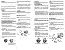
FRONT WHEEL TOE-IN/CAM BER
Your new tractor front wheel toe-in and
camber is set at the factory and is normal.
The front wheel toe-in and camber are not
adjustable. If damage has occurred to
affect the factory set front wheel toe-in or
camber, contact a Sears or other qualified
service center.
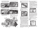
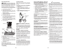
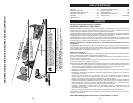
TO REMOVE WHEEL FOR REPAIRS
1. Block up axle securely.
2. Remove axle cover, retaining ring and
washers to allow wheel removal (rear
wheels have a square key - Do not lose).
3. Repair tire and reassemble.
NOTE: On rear wheels only: align grooves in
rear wheel hub and axle. Insert square key.
4. Replace washers and snap retaining ring
securely in axle groove.
5. Replace axle cover.
NOTE: To seal tire punctures and pre vent
flat tires due to slow leaks, purchase and
use tire sealant from Sears. Tire sealant also
pre vents tire dry rot and corrosion.
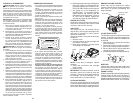
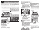
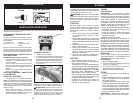
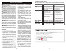
Weak or
Dead
Battery
Fully
Charged
Battery
TO START ENGINE WITH WEAK BAT TERY
WARNING: Lead-acid batteries gen er-
ate ex plo sive gases. Keep sparks, flame
and smoking ma te ri als away from bat ter ies.
Always wear eye pro tec tion when around
batteries.
If your battery is too weak to start the engine, it
should be recharged. (See "BATTERY" in the
MAINTENANCE section of this man u al).
If “jumper ca bles” are used for emer gen cy
starting, follow this pro ce dure:
IMPORTANT: Your tractor is equipped with
a 12 volt system. The other vehicle must also
be a 12 volt system. Do not use your tractor
battery to start other vehicles.
TO ATTACH JUMPER CABLES -
1. Connect one end of the RED cable to the
POSITIVE (+) terminal of each battery(A-
B), taking care not to short against tractor
chassis.
2. Connect one end of the BLACK ca ble
to the NEGA TIVE (-) terminal (C) of fully
charged battery.
3. Connect the other end of the BLACK
cable (D) to good chassis ground, away
from fuel tank and bat tery.
TO REMOVE CABLES, REVERSE ORDER -
1. BLACK cable first from chassis and then
from the fully charged battery.
2. RED cable last from both batteries.
0
0
6
6
3
Retaining
Ring
Washers
Square
Key
(Rear Wheel Only)
Axle
Cover
0
2
2
3
9
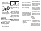
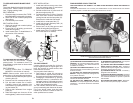
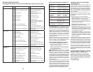
Adjustment Bolt
Neutral
Lock
Gate
Motion Control
Lever
TRANSAXLE MOTION CON TROL LEVER
NEUTRAL AD JUST MENT
The motion control lever has been pre set at the
factory; adjustment should not be necessary.
1. Loosen adjustment bolt in front of the
right rear wheel, and lightly tight en.
2. Start engine and move motion con trol
lever until tractor does not move forward
or backward.
3. Hold motion control lever in that position
and turn engine off.
4. While holding motion control lever in
place, loosen the adjustment bolt.
5. Move motion control lever to the neutral
(lock gate) position.
6. Tighten adjustment bolt securely.
NOTE: If additional clearance is needed to
get to ad just ment bolt, move mower deck
height to the lowest position.
After above adjustment is made, if the trac-
tor still creeps forward or backward while
motion control lever is in neutral position,
follow these steps:
1. Loosen the adjustment bolt.
2. Move the motion control lever 1/4 to 1/2
inch in the direction it is trying to creep.
3. Tighten adjustment bolt securely.
4. Start engine and test.
5. If tractor still creeps, repeat above steps
until satisfied.