


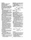
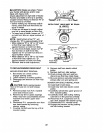
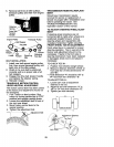
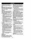

3. Remove belt from all idler pulleys,
transaxle pulley and then from engine
pulley.
Retainer
a
Drive
Tension
Handle
Engine Pulley Transaxle Pulley
_,_ Belt Keeper
Flat Idler
Belt
Keeper Keeper
Clutching
V-Idler Keeper Clutching Flat Idler
Idler
BELT INSTALLATION -
1. Install new belt around engine pulley
first, then around transaxle pulley and
lastly into all the idler pulleys.
2. Check to be sure belt is positioned
correctly and is on proper side of all
belt keepers.
3. Engage the drive belt tension handle
and replace the retainer spring.
4. Reinstall mower.
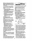
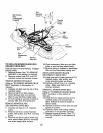
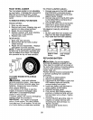
TRANSAXLE MOTION CONTROL
LEVER NEUTRAL ADJUSTMENT
The motion control lever has been preset
at the factory and adjustment should not
be necessary.
1. Park Tractor on level surface. Stop
tractor by turning ignition key to "OFP
position and engage parking brake.
2. Loosen the adjustment bolt in front of
the right rear wheel.
3. Move motion control lever to the
neutral position.
4. Tighten the adjustment bolt.
Adjustment Bolt
TRANSMISSION REMOVAL/REPLACE-
MENT
Should your transmission require
removal for service or replacement, it
should be purged after reinstallation and
before operating the tractor. See
"PURGE TRANSMISSION" in the
Operation section of this manual.
TO ADJUST STEERING WHEEL ALIGN-
MENT
If steering wheel crossbars are not
horizontal (left to right) when wheels are
positioned straight forward, remove
steering wheel and reassemble with
crossbars horizontal. Tighten securely.
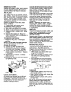
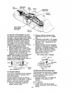
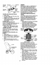
FRONT WHEEL TOE-IN ADJUSTMENT
Front wheel toe-in is required for proper
steering operation. Toe-in was set at the
factory and adjustment should not be
necessary. If parts in the front axle or
steering mechanism have been replaced
or damaged, check toe-in and adjust if
necessary.
TO CHECK TOE-IN -
1. Position front wheels straight ahead.
2. Measure distance between wheels at
front and rear of tires (dimensions "A"
and "B").
• Front dimension "A" should be 1/8" to
1/4" less than rear dimension "B".
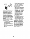
TO ADJUST TOE-IN -
1. Loosen jam nuts at adjustment
sleeves on tie rod.
2. Adjust tie rod until dimension "A" is
1/8" to 1/4" less than dimension "B".
3. Tighten jam nuts securely.
B w=.
_A "-
iustment
Jam Nuts
25