


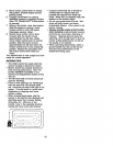
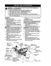
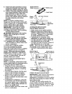
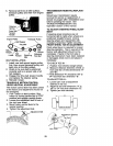

8. Install front plate assembly to tractor
suspension brackets and retain with
single loop retainer springs as shown.
9. Position front plate assembly between
front mower brackets. Raise deck and
plate assembly to align holes and
insert flanged pins. Secure pins with
double loop retainer springs between
the plate assembly and mower
brackets.
NOTE; To assist in locating hole in
flanged pin, the hole in pin is inline with
notch on head of pin. If necessary, move
mower side-to-side to give space
between plate and mower brackets.
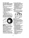
IMPORTANT: Check belt for proper
routing in all mower pulley grooves.
10.Engage belt tension rod by pushing
rod into locking bracket.
A CAUTION; Belt tension rod is spring
loaded. Have a tight grip on rod and
engage slowly.
11. Connect anti-sway bar to chassis
bracket under left footrest and retain
with double loop retainer spring.
12.If equipped, turn height adjustment
knob clockwise to remove slack from
mower suspension.
13. Raise deck to highest position.
TO LEVEL MOWER HOUSING
Adjust the mower while tractor is parked
on level ground such as a carport or
garage. Make sure tires are properly
inflated (See "PRODUCT SPECIFICA-
TIONS" section of this manual). If tires
are over or underinflated, you will not
properly adjust your mower.
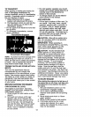
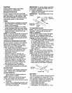
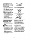
SIDE-TO-SIDE ADJUSTMENT WITH
BUBBLE LEVEL
NOTE: If necessary, check side-to-side
surface below tractor for levelness with a
long board and the bubble level.
• Using the lift lever, place mower in
position where no part of the mower,
including gauge wheels, is touching
the ground.
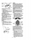
• From left side of tractor, find the level
decal on top of mower and place
bubble level on decal as indicated.
• Mower is level side-to-side when
bubble is between the two lines in the
bubble level.
• If adjustment is necessary, under left
hand footrest, turn lift link adjustment
nut (above yellow cap) in appropriate
direction to bring bubble between the
lines in the bubble level.
• Remove bubble level from mower and
store in a safe place.
Bubble Between
Lines __m/b Bubble Level
_ Level Decal
Brake .._ Left Hand Footrest
y_ Lift Link
ANd_ustment
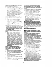
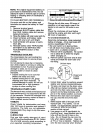
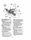
ALTERNATE SIDE-TO-SIDE
ADJUSTMENT METHOD
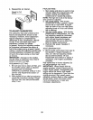
• Raise mower to its highest position.
• Measure height from bottom edge of
mower to ground level at front corners
of mower. Distance "A" on both sides
of mower should be the same.
• If adjustment is necessary, make
adjustment on one side of mower only.
• To raise one side of mower, tighten lift
link adjustment nut on that side.
• To lower one side of mower, loosen lift
link adjustment nut on that side.
NOTE: Each full turn of adjustment nut
will change mower height about 3/16".
• Recheck measurements after adjust-
ing.
Bottom Edge of BottomEdge of
M_rtoA__-_ Ground Mower toiroun d
Suspension
Arm
Lift Link
Jstment
Nut
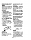
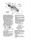
FRONT-TO-BACK ADJUSTMENT
IMPORTANT: Deck must be level side-to-
side. If the following front-to-back
adjustment is necessary, be sure to adjust
both front links equally so mower will stay
level side-to-side.
To obtain the best cutting results, the
mower blades should be adjusted so the
front tip is approximately 1/8" to 1/2" lower
than the rear tip when the mower is in its
21 highest position.