


SERVICE AND ADJU
i =l= i=l=l=Hl=l .......................................
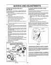
TO REPLACE MOTION DRIVE BELT
(See Fig. 26)
Park the tractor on level surface,. Engage parking brake_
For ease of service there is a belt installationguide decal on
bottom of left footrest.
o Remove mower (See 'q'O REMOVE MOWER" in this
section of this manual.)
BELT REMOVAL
= Engage parking brake (creates slack in belt)_
• Remove bert from clutching and fan idler pulleys..
° Loosen belt keeper above transaxle pulley.
° Remove belt from transaxie pulley_
° Remove belt from engine pulley and front V-idler pul-
ley.,
° Pull belt out of all belt keepers and remove from tractor°
BELT INSTALLATION -
• Place V part of belt into grooves on engine pulley and
front V-idler, making sure to route belt inside of all belt
keepers.,
• Route belt on right side, coming from V-idler, towards
back of tractor, above midspan belt keeper' and to top
of transaxle pulley.
° Route belt on left side, coming from engine pulley,
towards back of tractor and through loop in mldspan
belt keeper.
= Place V part of belt intogrooves on transaxle and fan
idterpulleys, making sure to route belt insideof all belt
keepers°
° Retighten belt keeper above transaxle pulley.
• Place belt around clutching idlers as shown, making
sure to route belt inside of all belt keepers.,
- Check to be sure belt is positioned correctly and ison
proper side of art belt keepers.
o Reinstall mower,.
IMPORTANT; CHECK BRAKE ADJUSTMENT.
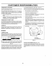
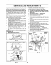
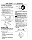
TRACTOR V-BELTDRIVE SCHEMATIC
VIEWED FROM L.H. SIDE OF TRACTOR
CLUTCHING TRANSAXLE
BELT PULLEY
KEEPER
ENGINE
PULLEY
V-IDLER KEEPER
KEEPER BELT
TWISTS
BELT FAN
KEEPER IDLER
AS VIEWED FROM BOTTOM
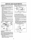
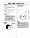
TO ADJUST MOTION CONTROL LEVER
(See Fig. 27)
The motion control leverhas been presetat the factory and
adjustment should not be necessary_
If for any reason the motion control lever will not hold its
positionwhile at a selected speed, itmay be adjusted at the
friction pack located on the right side of chassis,
• Park tractor on level surfacer Stop tractor by turning
ignition key to "OFF" position and engage parking
brake_
= Place motion control lever in neutral (N) position_
o While holding locknut, toosen jam nut
° Tighten tocknut 1/4 turn,
• White holding Iocknut, tighten jam nut securely_
NOTE: if for any reason the effort to move the motion
control lever becomes too excessive, reverse the above
adjustment procedure by loosening iocknut 1/4 turn_
Road test tractor after adjustment and repeat procedure if
necessary_
LOCKNUT
,JAM NUT
FIG. 27
TRANSMISSION REMOVAL/REPLACEMENT
Should your transmission require removal for service or
replacement, itshould be purged after reinstallation before
operating the tractor. See "PURGE TRANSMiSSiON" in
Operation section of this manual,
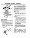
TO ADJUST STEERING WHEEL ALIGNMENT
if steering wheel crossbars are not horizontal (left to right)
when wheels are positioned straight forward, remove steer-
ir_,gwheel and reassemble per instructions in the Assembly
section of this manual
FIG. 26 24