


SERVICE AND ADJUSTMENTS
TO ADJUST STEERING WHEEL ALIGNMENT
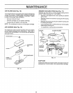
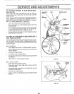
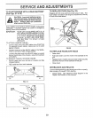
TO ADJUST MOTION CONTROL LEVER (See
Fig. 29)
"NEUTRAL" position of the motion control lever has been
preset at the factory and adjustment should not be neces-
sary
Ifyour unit tends to "creep" when the motion control lever
is in "NEUTRAL" position, adjust the neutral lever position
as follows:
FORWARD ADJUSTMENT-
Drive unit forward on a level surface
Move motion control lever to the left and back until it
stops against forward adjustment plate and release
lever.
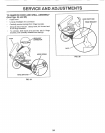
If unit "creeps" forward or backward, turn engine off
and set parking brake.
From underside of fender, loosen the two (2) bolts se-
curing forward adjustment plate and move plate 1/16"
opposite the direction the unit "creeps":
Forward "creep", move plate backwards 1/16 inch
Reverse "creep", move plate forward 1/16 inch
Retighten bolts securely
Repeat forward drive test and, if necessary, readjust
until "creep" is eliminated.
REVERSE ADJUSTMENT-
Drive unit in reverse on a level surface.
Move motion control lever to the right and forward until
it stops against reverse adjustment plate and release
lever
If unit "creeps" forward or backward, turn engine off
and set parking brake
Loosen and move reverse adjustment plate in the
same manner as forward adjustment plate described
above:
Forward "creep", move plate backwards 1/16 inch
Reverse "creep", move plate forward 1/16 inch.
Retighten bolts securely
Repeat reverse drive test and, if necessary, readjust
until "creep" is eliminated
If "creep" cannot be eliminated by the above adjustments,
corrtact your nearest Sears Service Center.
FORWARD ADJUSTMENT PLATE
BOLTS
REVERSE ADJUSTMENT PLATE
MOTION
CONTROL
LEVER
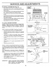
If steering wheel crossbars are not horizontal (left to right)
when wheels are positioned straight forward, remove steer-
ing wheel and reassemble per instructions in the Assembly
section of this manual.
FRONT WHEEL TOE-IN/CAMBER
The front wheel toe-in and camber are not adjustable on
your unit, If damage has occured to affect the front wheel
toe-in or camber, contact your nearest Sears Service
Center
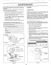
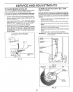
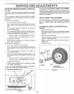
TO REMOVE WHEEL FOR REPAIRS (See
Fig. 30)
Block up axle securely.
Remove hub cap, retaining ring and washers to allow
wheel removal (rear wheel contains a square key- Do
not lose).
Repair tire and reassemble
On rear wheels only: align grooves in rear wheel hub
and axle. Insert square key
Replace washers and snap retaining ring securely in
axle groove
Replace hub cap.
WASHERS
RETAINING
RING
HUB CAP
I
_SQUARE KEY
(REAR WHEEL ONL_
FIG. 30
FIG. 29
22