


a
o
SERVNCE AN ADJUSTMSNTS
.._==H..u= ...11.. N==u,i i., u=
i.u.,. =
CAUTION: BEFORE PERFORMING ANY SERVICE OR ADJUSTMENTS:
° Depress clutch/brake pedal fully and set parking brake.
. Place gearshift lever in "NEUTRAL" position.
. Place attachment clutch in "DISENGAGED" position.
Turn ignition key "OFF" and remove key.
Make sure the blades and all moving parts have completely stopped.
Disconnect spark plug wire from spark plug and place wire where it cannot come in contact with
plug.
TRACTOR
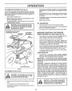
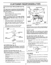
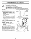
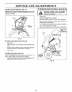
TO REMOVE MOWER (See Fig. 17)
Mower wiltbe easier toremove from the rightside of tractor,
• Place attachment clutch in "DISENGAGED" position.
• Move attachment lift lever forward to lower mower to its
lowest position.
• Roll belt off engine pulley.
• Disconnect clutch rod from clutch lever by removing
retainer spring,
• Disconnect suspension arms from rear deck brackets
by removing retainer springs_
, Disconnect front links from deck by removing retainer
springs_
• Raise lift lever to raise suspension arms. Slide mower
out from under tractor,
IMPORTANT; iF AN ATTACHMENT OTHER THAN THE
MOWER IS TO BE MOUNTED TO THE TRACTOR, TIdE
R.H, AND Loll, SUSPENSION ARMS MUST BE REMOVED
FROM TRACTOR.
TO INSTALL MOWER (See Fig. 17)
• Raise attachment lift lever to its highest position°
• Slide mower under tractor with discharge guard to right
side of tractor.
• Lower lift lever to its lowest position.
. Install mower in reverse order of removal instructions.
NOTE: The mower clutch rod has a trunnion that has been
preset at the factory for optimum mower performance. DO
NOT MOVE THE TRUNNION ON THE CLUTCH ROD. If
for any reason the trunnion has been moved on the clutch
rod, it must be reset to correct position (parallel with clutch
rod) and measure 10-11/32" (Check dimension on edge of
flat work surface as shown)
Be sure to tighten trunnion nut securely against trunnion
after making any adjustments.
TRUNNION
RETAINER
SPRINGS
SEE NOTE ABOVE
CORRECT
)_TRUNNION
POSITION
"_--PARALLEL
CLUTCH
ROD
RETAINER
SPRING
RETAINER
SPRINGS
ENGINE
PULLEY
FIG. 17
18