


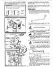
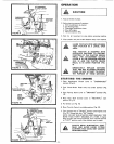
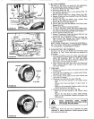
DISCHARGING
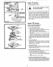
FIGURE 13
CHARGING
- _ • _. •
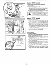
1,,Connect each end of the RED cable to the POSITIVE (+)
terminals of each battery (taking care not to shor_t against
chassis),
2, Connect one end of the BLACK cable to the NEGATIVE
(-) terminal of fully charged battery.
3. Connect the other end of the cable to ENGINE BLOCK
or good CHASSIS GROUND on tractor (away from Gas
Tank or Battery),
4,_Disconnect cables in reverse order':
a, Engine Block or chassis of tractor_
b_ Negative terminal of fully charged battery_
c. Positive terminals,,
1
DO NOT USE YOUR TRACTOR BAT- I
TERY TO START OTHER VEHICLES.
I
MAINTENANCE
To keep your tractor running better, longer; perform nec-
essaryservice using the following Maintenance Schedule.
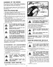
Each time you start your tractor, check your Ammeter (Fig.
13). The needle should move towards the + (charging) mark
indicating the battery is being charged as you operate the
tractor.
DISCONNECT SPARK PLUG WIRES TO
PREVENT ACCIDENTAL STARTING BE-
FORE MAKING ANY INSPECTION, AD-
JUSTMENT OR REPAIR (EXCEPT CAR-
BURETOR).
/
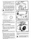
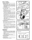
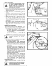
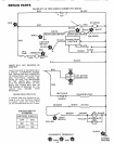
DIAGNOSTIC TERMINAL ADAPTEF
FIGURE 15
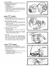
STARTING YOUR TRACTOR WITH
A LOW BATTERY
If your Battery is too tow to start the engine it should be
II II .
recharged. If Jumper Cables are used for emergency starting
foilow this procedure: NOTE: YOUR TRACTOR IS EQUIP-
PED WITH A 12 VOLT NEGATIVE GROUNDED SYSTEM
THE OTHER VEHICLE MUST ALSO BE A 12 VOLT NEGA-
TIVE GROUNDED SYSTEM.
LEAD-ACID BATTERIES GENERATE EX-
PLOSIVE GASES. KEEP SPARKS, FLAME,
AND SMOKING MATERIALS AWAY
FROM BATTERIES, ALWAYS WEAR EYE
PROTECTION AROUND BATTERIES.
DAILY MAINTENANCE
Make sure all nuts on bolts are tight and cotter pins are secure.
Observe all safety precautions° Keep Tractor well lubricated
(refer to page 8)_
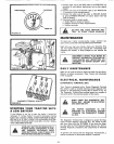
ELECTRICAL MAINTENANCE
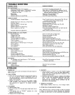
DIAGNOSTIC TERMINAL BOX
Your Tractor is equipped with a Tractor Diagnostic Terminal
Box which is used to simplify electrical system diagnosis. The
Iocation of the Diagnostic Terminal Box is shown in Fig. 14.
The Diagnostic Terminal Box provides access to a number of
test points within the electrical system of the tractor.
WHEN USING THE DIAGNOSTIC TER-
MINAL BOX - ENGINE TO BE STOPPED
AND IGNITION OFF,
USE PROPER EQUIPMENT IN THE
CHECKING OF ELECTRICAL SYSTEM
THROUGH THE DIAGNOSTIC TERMIN-
AL BOX.
The Diagnostic Terminal Box is designed to accept the Diag-
nostic Terminal Adapter (optional) (Fig° t5), which is avail-
able from Sears (Part No. 677A823)_ If you order the Adap-
ter, also order the Test Procedure Manual (Manual Nor 8441J),
showing diagnostic procedures and components of electrical
circuits°
To perform the testing with the Diagnostic Terminal Box, a
quality multimeter or automotive analyzer is required.
_6-