


-
------
----
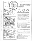
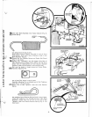
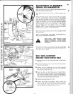
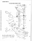
FIGURE
7A
RETAINER
_
SPRING~IDLER
B
~
SHAFT
ASSEMBLY
FIGURE 8
0
,--
ADJUSTING
PIN
\\
/
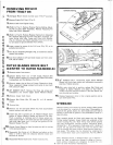
SNUBBER
PULL
ROD
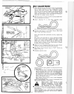
BELT
ADJUSTMENT
1. Adjust belt
by
turning Adjusting Pin (Fig. 7) counterclock·
wise
to
tighten; clockwise
to
loosen.
Engage
Mower Clutch
Control Lever (push forward). Belt
is
properly adjusted
when Belt
can
be
squeezed
together
with
thumb
and
fo
re
finger
(without
undue pressure) midway between Engine
Pulley
and
Idler
Sheaves.
After
first
2 hours
of
mowing, re·
check Belt
fo
r proper tension (Fi
g.
9).
2.
Belt
from
center
to
outside mandrels
is
spring loaded there·
for
e no adjus
tment
is
n
ecessary
.
3. Attach Adjusting Pin
to
Id
ler Shaft Assembly
us
ing:
one
of
the large Retainer Springs found in
bag
of
parts.
4 .
Assem
ble Belt Gui
de
to
Idler Shaf
t.
Pos
ition
Belt
Guide
Tab in
Idler
Arm
Notch (Fig. 8).
Secure
Belt Guide
with
Lockwasher and Nut. Tighten
Nut
secure
l
y.
Belt Guide must clear
belt
by
1/16
to
1/8
inch at points
A and B when
clutch lever
is
engaged
(belt tight) in both
highest and lowest cutting position
of
mower.
If
Belt
Guide
does
not
clear by 1/16
to
1/8
inch,
Belt
Guide
can
be bent
sl
igh
tly
at points A
and
B
with
pliers
or
wrench
to
achieve the proper clearance.
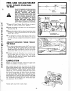
5.
(Refer
to
F
ig
.
4).
Reassemble
Belt Guard
to
engine. Secure
with
th
e
two
Retainer Spri
ngs
previously removed.
6.
Place
Mow
er Clutch Control Lever in
"OU
T" Position
as
shown in Fig. 7A.
7. Comp
le
te
assembl
y using:
remaining Retainer
Spring,
Wash
er and Adjusting Pin found
in
bag
of
parts.
a.
Thread
Adju
sting
Pin
on Snubber Pull Rod
until
Adjust-
ing Pin
will
enter hole in Idler Shaft Assembly (Fig. 8).
Remove Adjusting
Pin
from
hole. Turn Adjusting Pin
counterclockwise
6 complete turns
and
slip
Washer
on
Pin. Insert Pin in Idler Shaft Assembly. NOTE: Mower
Clutch Control Lever
can
be
pulled
ahead
to
assemb
le.
Secure
with
Retainer Spring.
When Mower Clutch Control Lever
is
fully
disengaged,
bl
ades
wi
II
stop
quickly
.
NOTE:
TRACTOR
WILL
NOT
ST
ART
IF
SNUBBER
PULL
ROD IS
NOT
PROPERLY ADJUSTED.
MAKE
SURE
THAT
BRAKE
IS NOT
AGAINST
MANDREL
PULLEY
WHEN
MOWER
IS
ENGAGED
(LEVER
PUS
H-
ED FORWARD TO "
IN
" POSITION).
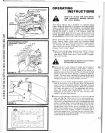
8.
If
Snubber Pull Rod is
ever
removed,
be
sure
it
is
r
eassembl-
ed
as
shown in Fig. 9
to
Snubber Weldment
and
secured
with
Cotter Pin.
NOTE: SNUBBER
PULL
ROD MUST
BE
POSITIONED
UNDER MOWER
DRIVE
BELT
WITH
SLIGHT
BEND
IN
ROD DOWNWARD.
another free manual from www.searstractormanuals.com