


6
IMPORTANT: This unit is shipped with engine oil, but
without gasoline, in the engine. After assembly, see
OPERATION section of this manual for fuel selection
and fill-up.
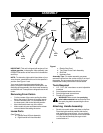
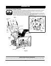
NOTE: To determine right and left hand sides of your
snow thrower, stand behind the unit in the operator’s
position. See Figure 1 inset.
Your snow thrower has been assembled at the
factory, except the handle and the handle panel, the
discharge chute assembly, the chute crank assembly
and the shift rod. These parts are shipped loose in the
carton.
Removing From Carton
• Cut the corners of the carton and lay the sides
flat on the ground. Remove all packing inserts.
• Remove all loose parts. For a complete list of
the loose parts, refer to the following section.
• Move the snow thrower out of the carton.
• Make certain all parts and literature have been
removed before discarding the carton.
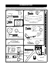
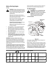
Loose Parts
(See Figure 1.)
a. Handle Panel & Chute Assembly
b. Right Hand & Left Hand Handles
c. Electric Start Cord
d. Two-Piece Chute Crank Assembly
e. Shift Rod
f. Hardware Pack
Assembly Tips: For easier assembly purposes,
remove the chute from the carton and lay it on top of
the engine. Do not unwrap the chute till you have
installed the handle panel and the clutch cables.
Tools Required
1. 1/2" , 7/16”, 3/8” wrenches or a set of adjustable
wrenches
2. Set of standard head screw drivers
3. Set of philips head screw drivers
4. Funnel to fill up gasoline
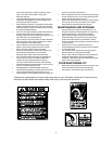
WARNING: Make certain the spark plug
wire is disconnected and moved away from
the spark plug before assembling the snow
thrower.
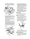
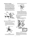
Attaching Handle Assembly
• Stretch out control cables and place on the floor.
Place the right handle in position with the flat
side against the snow thrower. You can identify
the right handle by the traction drive control label
on it and the left handle by the auger clutch
control label on it.
ASSEMBLY
Left
Right
Front
Rear
Figure 1
Handle
Panel
Chute
Shift
Rod
Chute
Crank
Handles
Electric
Start Cord