


20
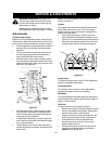
WARNING: Always stop the engine, dis-
connect spark plug wire and move it away
from the spark plug before performing any
adjustments or repairs.
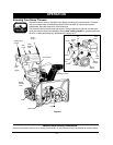
Never attempt to clean the chute or make
any adjustments while the engine is running.
Adjustments
Traction Drive Control
Refer to the Final Adjustment section of the Set-Up
Instructions to adjust the traction drive control. If you
are not sure of proper adjustment, check as follows.
• Drain the gasoline or place plastic film under the
gas cap if the snow thrower has already been
operated.
• Tip the snow thrower forward and remove the
four self-tapping screws that hold the frame
cover underneath the snow thrower.
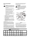
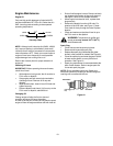
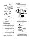
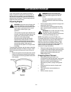
• With the traction drive control released, make
sure that there is clearance between the friction
wheel and the friction plate in all positions of the
shift lever. See Figure 22.
Figure 22
• With the traction drive control engaged, make
sure that the friction wheel is making contact
with the friction plate. Also make sure that the
overtravel spring is stretched.
• If adjustment is necessary, loosen the jam nut
on the traction drive cable and thread the cable
in or out as necessary.
• Tighten the jam nut to secure the cable when
correct adjustment is reached. Reassemble the
frame cover.
Sprocket
Shaft
Drive
Cable
Pivot
Rod
Friction
Plate
Drive Shaft
Friction
Wheel
NOTE: If you placed plastic under the gas cap, be
certain to remove it.
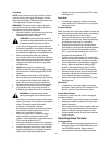
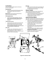
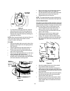
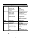
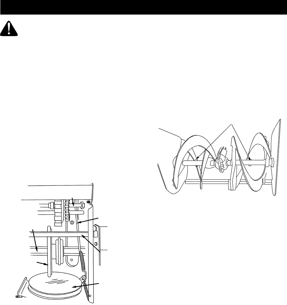
Augers
The augers are secured to the spiral shaft with two
shear bolts and hex lock nuts. If you hit a foreign
object or ice jam, the snow thrower is designed so
that the bolts will shear.
• If the augers will not turn, check to see if the
bolts have sheared. Replace if necessary. See
Figure 23. Two replacement shear bolts and hex
lock nuts have been provided in Group D of the
hardware pack which is illustrated on page 5.
Figure 23
Auger Clutch
To adjust the auger clutch, refer to Final Adjustment
section of Assembly Instructions.
Chute Assembly
The distance snow is thrown can be adjusted by
adjusting the angle of the chute assembly.
Skid Shoe
The space between the shave plate and the ground
can be adjusted by adjusting the skid shoe. Refer to
page 11 of this manual.
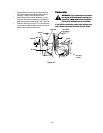
Shift Rod
To adjust the shift rod, proceed as follows.
• Remove the hairpin clip and flat washer from the
ferrule underneath the shift panel. Remove the
ferrule from the hole in the shift lever.
• Place the shift lever on the handle panel in the
sixth (6) speed position (all the way forward).
• Push down on the shift rod (and shift arm
assembly) as far as it will go. Hold it in this
position. See Figure 24.
• Thread the ferrule up or down the shift rod as
necessary until the ferrule lines up with the
upper hole in the shift lever.
Shear Bolt
SERVICE & ADJUSTMENTS