


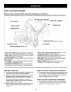

ATTACHING CLUTCH/IDLER ASSEMBLY
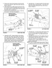
IF YOUR MOWER DECK SIZE IS OTHER THAN 48"
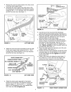
• Before attaching the clutch idler assembly to the
tractor, measure the outer diameter of the tractor's
engine pulley. If the diameter of the pulley is less
than 6", move the 3/32" hairpin clip in the L.H.
adjusting chain from link #8 to link #5. (Links are
counted from the end of the chain attached to the
spring).
LINK #5 IN
L.H. CHAIN
R.H. CHAIN
FIGURE 7
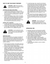
Attach the rear of the clutch/idler assembly to the
tractor frame by sliding the notched arms of the
assembly onto the shoulder bolts assembled to the
frame brackets. Lift the front of the assembly,
positioning the upper idler pulley so that it clears
the engine pulley. Attach the front of the assembly
to the hanger brackets using two pivot lock pins
and 1/8" hairpin clips. See figure 8.
PIVOT LOCK PIN
FIGURE 8 RIGHT SIDE VIEW
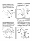
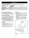
ASSEMBLY OF SNOW THROWER
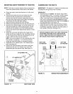
Place the lift handle into the lift bracket on the right
side of the snow thrower. Fasten the handle to the
bracket using two 5/16" x 1-3/4" hex bolts, 5/16"
lock washers and 5/16" hex nuts. See figure 9.
LIFT HANDLE
5/16" x 1-3/4"
\
\) HEX BOLT
LIFT BRACKET
5/16" HEX NUT
5/16" LOCK
WASHER
FIGURE 9 RIGHT SIDE VIEW
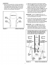
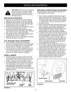
NOTE: Be sure the lift release cable's plastic covering
remains inserted into the trigger assembly while
completing the next step.
• Push the lift handle down into the locked position.
Insert the end of the cable wire into the hole in the
lift rod. Place the threaded fitting into the slot in the
lift bracket, with one hex nut above and one hex
nut and the lock washer below the slot. Tighten the
nuts, adjusting them to eliminate slack in the cable
wire. See figure 10. Refer also to the Service and
Adjustments section on page 16 in this manual.
LIFT RELEASE
CABLE
8
TRIGGER
ASSEMBLY
FIGURE 10
HEX NUT
LOCK
WASHER
HEX NUT
__ WIRE
LIFT
ROD
RIGHT SIDE VIEW