


MOUNTING SNOW THROWER TO TRACTOR ASSEMBLING THE BELTS
NOTE: The help of another person may be required to
mount the snow thrower to the front of the tractor.
• Place the tractor and snow thrower on a flat, level
surface.
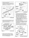
• Remove the plastic tie from the auger belt and
extend the belt out behind the snow thrower,
making sure the belt remains assembled around
the top of the large auger drive pulley and passing
underneath the two side idler pulleys.
• Align the tractor behind the snow thrower.
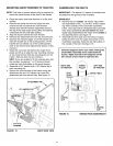
• Remove the attachment pin from the snow thrower.
• Squeeze the release trigger on the lift handle and
raise the handle out of the locked position. (If the
handle will not release out of the locked position,
refer to the Service and Adjustments section of this
manual.)
• Grasp the round bar just behind the auger drive
pulley and lift up to align the rear mounting notches
on the snow thrower with the mounting pins on the
tractor. Slide the pins into the notches.
HINT: If you are unable to fit the mounting pins into
the notches, try placing 1" or 2" blocks of wood
under the front skid shoes on the snow thrower.
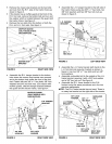
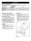
• Assemble a 3/4" washer and a 1/8" hairpin clip to
each mounting pin.
• Secure the snow thrower to the tractor using the
attachment pin and 1/8" hairpin clip. Insert the
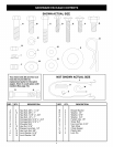
attachment pin from the left side. See figure 15.
I
[]
A'rrACHMENT PIN
1/8" HAIRPIN CLIP '''''v
I
1
814" FLAT
WASHER
IMPORTANT: The tapered "V" section of the belts must
be seated into the grooves of the V-pulleys.
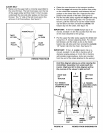
DRIVE BELT
• Remove the two outside 1/8" hairpin clips which
are assembled to the L.H. and R.H. tension adjust-
ing chains outside of the clutch idler assembly
frame. (The clips will be reinstalled after both belts
have been assembled.) Do not remove the 3/32"
hairpin clips assembled to the chains on the inside of
the assembly frame. See figure 16.
• Assemble the drive belt onto the tractor's engine
pulley and then onto the upper rear pulley on the
clutch/idler assembly. Keep the flat idler pulley on
the outside of the belt. See figure 16.
Hold this diagram above you while viewing the
Clutch/Idler Assembly from underneath the
tractor. Right and left in this diagram will be
the reverse of the viewer's right and left.
I
RIGHT SIDE ENGINE LEFTSIDE
OF TRACTOR PULLEY OF TRACTOR
FLAT _ _DRIV V-BELT
IDLER
PULLEY
c_
,
I' '1 C)
1/8"
HAIRPIN
CLIP
1/8"
HAIRPIN
CLIP
FIGURE 16 VIEWED FROM UNDERNEATH
FIGURE 15 RIGHT SIDE VIEW
10