


4
Call 1-866-576-8388 for missing parts or assembly help
DO NOT RETURN TO STORE
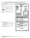
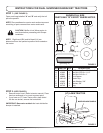
STEP 3: (SEE FIGURE 4)
• Place plug (D) on a work bench or solid table and
push end of bumper down onto plug. Repeat for all
four plugs.
FIGURE 4
PLUG (D)
BUMPER
PUSH DOWN
WITH EVEN
PRESSURE
WORK BENCH
OR SOLID TABLE
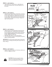
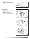
STEP 4: (SEE FIGURE 5)
• Attach left mounting bracket to hole shown in left side
of tractor frame using a carriage bolt (A) and whizlock
nut (C). Align middle hole in bracket with empty hole
in tractor frame. Tighten whizlock nut (C) only enough
to keep bracket in alignment until step 5. Repeat for
right mounting bracket.
WHIZLOCK
NUT (C)
LEFT MOUNTING
BRACKET
BUMPER STOPS
FACE OUT
ALIGN THESE HOLES
CARRIAGE
BOLT (A)
LEFT SIDE VIEW FIGURE 5
(GT) FRAME SHOWN
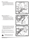
STEP 5: (SEE FIGURE 6)
• Fasten bumper to mounting bracket using a hex bolt
(B), pivot spacer (E), a locking lever and a whizlock
nut (C) as shown. The pivot spacer inserts into hole in
bumper. Tighten both nuts on mounting bracket at
this time. Repeat for other side.
• Assemble plastic grips (F) onto locking levers.
• Lift up on bumper until pins in locking levers snap into
holes in mounting brackets.
IMPORTANT: You must lower bumper before raising tractor
hood. Pull out on locking levers and push bumper down as
far as it will go.
FIGURE 6 LEFT SIDE VIEW
PIVOT
SPACER (E)
HEX BOLT (B)
PIN
LOCKING
LEVER
GRIP (F)
WHIZLOCK
NUT (C)
STEP 6: (SEE FIGURE 7)
• Replace the front screws and browning shield you
removed in Step 2 as shown.
FIGURE 7 LEFT SIDE VIEW
REPLACE
BROWNING SHIELD
REPLACE
FRONT SCREWS
CAUTION! Bumper may get hot when
tractor is running! Allow bumper to cool
down before grabbing hold of bumper.