


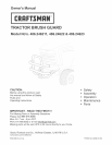

STEP 3: (SEE FIGURE 3}
IMPORTANT: Do not remove any bolts from the tractor
frame while the mower deck is raised. Misalignment of
holes in frame could result.
Lower mower deck to rest on ground.
Remove bolts from mounting holes on both sides of
tractor frame. Use a mounting bracket to help identify
holes.
(GT) FRAME
REMOVE THESE BOLTS
(LT) FRAME
REMOVE THESE BOLTS
)
NOT ALL (LT) FRAMES
HAVETHINSBRACKET
FIGURE 3
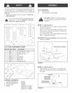
STEP 4: (SEE FIGURE 4}
Attach left mounting bracket to hole shown in left
side of tractor frame using bolt (C), lock washer (H)
and fiat washer (G). Align middle hole in bracket
with empty hole in tractor frame and tighten bolt (C)
to hold bracket in place. Repeat for right mounting
bracket.
(GT) FRAME SHOWN
LEFT MOUNTING
BRACKET
ATTACH TO
THRS HOLE
BUMPER STOPS
FACE OUT
FLAT
WASHER BOLT
(G} (C)
LOCK
WASHER
(H)
FIGURE 4
AUGN THESE HOLES
LEFT S_DE VIEW
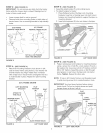
STEP 5: (SEE FIGURE 5)
o Assemble plastic grips (F) onto locking levers,
To attach bumper to tractor:
1. Place flattened ends of bumper onto mounting
brackets. Insert pin of locking lever into front hole in
bumper and mounting bracket to support bumper on
mounting bracket.
2. Insert pivot spacers (E) into rear holes in bumper.
PUVOT
SPACER
(E)_
LOCKING LEVER
J
FIGURE 5
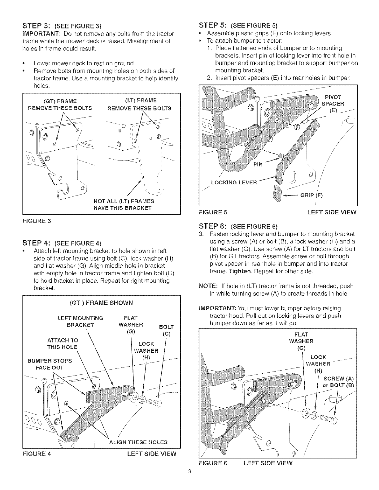
STEP 6: (SEE FIGURE 6)
3. Fasten locking lever and bumper to mounting bracket
using a screw (A) or bolt (B), a lock washer (H) and a
flat washer (G). Use screw (A) for LTtractors and bolt
(B) for GT tractors. Assemble screw or bolt through
pivot spacer in rear hole in bumper and into tractor
frame. Tighten. Repeat for other side.
NOTE: ff hole in (LT) tractor frame is not threaded, push
in while turning screw (A) to create threads in hole.
IMPORTANT: You must lower bumper before raising
tractor hood. Pull out on locking levers and push
bumper down as far as it will go.
FLAT
WASHER
(G)
LOCK ...........
WASHER
SCREW (A)
or BOLT (B)
FIGURE 6 LEFT SIDE VIEW