


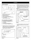
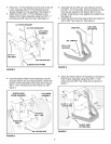


• PlacetheL.H.PivotBracketontotheendof the Lift
LeverAssembly(theR.H.PivotBracketcomes
alreadyinstalledontheassembly).SeeFigure4.
• AttachtheR.H.andL.H.PivotBracketstothe
SleeveHitchFrameAssemblyusingfour3/8"x 1"
hexboltsand3/8"hexlocknuts.SeeFigure4.
LH. PIVOT BRACKET
R.H. PIVOT BRACKET
LIFT LEVER
ASSEMBLY
3/8-16 x 1"
HEX BOLT
3/8" NYLOCK NUT
SLEEVE HITCH FRAME
FIGURE 4
• Assemble the two 5/8" jam nuts halfway onto the
two 5/8" x 2-1/2" hex bolts. Screw the bolts into the
nuts that are welded to the Sleeve Hitch Lift As-
sembly. Snug the jam nuts against the welded nuts.
See figure 6.
• Install the hitch pin in the sleeve hitch and secure it
with a 5/32" hair cotter pin. See figure 6.
5/32" HAIR
HITCH PIN
COTTER PIN
5_"JAM NUT
5/8"x 2-1/2"
HEX BOLT
FIGURE 6
Hook the Sleeve Hitch Frame Assembly onto the
shoulder bolts in the mounting brackets. Attach the
bottom of the Assembly to the tractor hitch using a
5/8" x 1-3/4" hex bolt and a 5/8" nylock nut. See
figure 5.
LIFT LEVER
FIGURE 5
Attach the Sleeve Hitch Lift Assembly to the Sleeve
Hitch Frame Assembly using three 5/8" x 1-3/4"
clevis pins and 5/32" hair cotter pins as shown in
figure 7.
......... -iiiiiiiiiiii.......
\
,,+(3)3/8"x 1-314"
: CLEVIS PINS
(3) 5/32" HAIR
COTTER PINS
FIGURE 7
5