


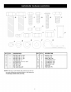


CARTON CONTENTS
1
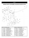
1. Sleeve Hitch Frame Assembly
2. Mounting Brackets (2)
3. Sleeve Hitch Lift Assembly
4. Hitch Pin with 5/32" Hair Cotter Pin
5. Lift Lever Assembly (with R.H. Pivot Bracket)
6. L.H. Pivot Bracket
Hardware Package (see page 3)
TOOLS REQUIRED FOR ASSEMBLY
(1) 1/2" Wrench or Adjustable Wrench
(2) 9/16" Wrenches or Adjustable Wrenches
(1) 5/8" Wrench
(1) 11/16" Wrench
(1) 3/4" Wrench or Adjustable Wrench
(1) 15/16" Wrenches or Adjustable Wrenches
4
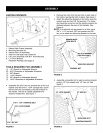
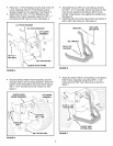
Assemble the 5/16" hex nut and then the 5/16" lock
washer onto the 5/16" x 1-3/4" carriage bolt. Screw
the bolt into the nut welded to the stop bracket on
the handle. The bolt is a depth adjustment for
attached implements. See figure 1.
5/16" HEX NUT
5/16" x 1-3/4" CARRIAGE BOLT
5/16" LOCK WASHER
• Remove the nuts from the two bolts in each side of
the tractor, leaving the bolts in place. See figure 2.
• Attach the Mounting Brackets to the bolts using the
original nuts and two 3/8" flat washers. The brack-
ets should be turned so that the bends increase the
distance between the rear of the brackets. See
Figure 2.
NOTE: If no bolt and nut are present in a hole, use a
3/8" x 1-1/4" hex bolt, 3/8" lock washer and 3/8"
hex nut to attach the Mounting Bracket to the hole.
\
MOUNTING BRACKET
ORIGINAL NUT
FIGURE 2
Assemble a shoulder bolt to each mounting bracket
using a 1/2" lock washer and 1/2" hex nut. See
figure 3.
1/2" LOCK WASHER 1/2" HEX NUT
/
\\ \\\
SHOULDER BOLT
MOUNTING BRACKET
FIGURE1 FIGURE3
4