6
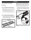
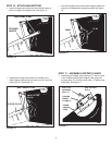
STEP 4 - ATTACH L.H. BRUSH ASSEMBLY
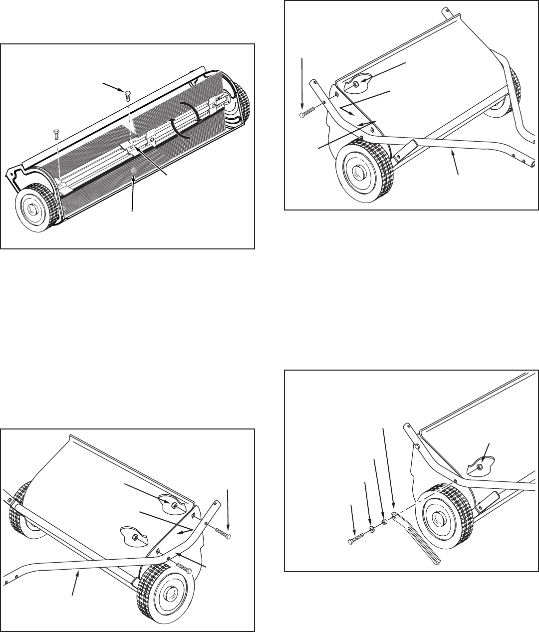
• Attachthebrushassemblywiththeredbrushretainer
totheleftendofthebrushshaftusingtwohexbolts(D)
andnylocknuts(H).Thebrushretainermarkedwithred
inkmustbeplacedtothemiddle of the sweeper. See
gure3.
• Turnawheeltorotatethebrushes.(Thewheelsdrive
thebrushesinonedirectiononly.)Theoverlapbristles
shouldbeonthebacksideofthebrushasitrotates.
FIGURE 3
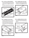
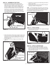
STEP 5 - ASSEMBLE LEFT HITCH TUBE
• Thehitchtubesarestampedwitha"77L"forthe
lefttubeanda"76R"fortherighttube.Thesweeper
housingismarkedwithan"L"ontheleftwithside
andan"R"ontherightside.Seegures4and5.
• Holdthelefthitchtubeagainsttheleftsideofthe
sweepersothatthe"77L"onthetubefacesaway
fromthesweeper.Attachthehitchtubeusingtwo
hexbolts(C)andnylocknuts(I).Do not tighten yet.
Seegure4.
HEX BOLT (C)
HITCH TUBE (L.H.)
NYLOCK NUT (I)
TUBE
MARKED
“77L”
HOUSING
MARKED “L”
FIGURE 4
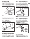
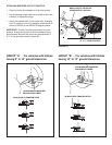
FIGURE 5
HEX BOLT (C)
HITCH TUBE (R.H.)
NYLOCK NUT (I)
TUBE
MARKED
“76R”
HOUSING
MARKED “R”
STEP 6 - ASSEMBLE RIGHT HITCH TUBE
• Holdtherighthitchtubeagainsttherightsideofthe
sweepersothatthe"76R"onthetubefacestoward
thesweeper.Attachthehitchtubeusingonehexbolt
(C)andnylocknut(I).Do not tighten yet.Seegure5.
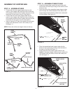
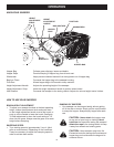
STEP 7 - ASSEMBLE HEIGHT ADJ. STRAP
• Attachtheheightadjustmentstraptothehitchtube
usingahexbolt(B),thespacerbushing(M),aat
washer(K)andanylocknut(I).Seegure6.Do not
tighten yet.
FLAT WASHER (K)
SPACER
BUSHING (M)
HEX BOLT (B)
NYLOCK NUT (I)
HEIGHT ADJ. STRAP
FIGURE 6
HEX BOLT (D)
NYLOCK NUT (H)
BRUSH RETAINER
MARKED RED


