


6
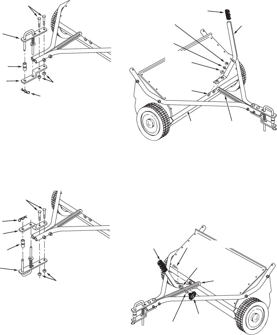
FIGURE 6
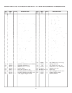
FIGURE 5
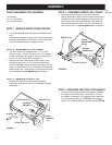
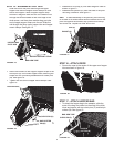
STEP 9 - ATTACH KNOB
•
Place the tooth-lock washer (I) between the height
adjustment handle and the height adjustment strap.
Insert the carriage bolt (D) through the handle, the
tooth-lock washer and the strap. Assemble the fl at
washer (H) and the plastic knob (U) onto the end of
the bolt and tighten. See fi gure 6.
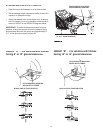
STEP 7 - TIGHTEN BOLTS
•
Tighten
the four bolts in fi gure 1 that fasten the hitch
tubes to the sweeper housing. Next,
tighten
the two
bolts in fi gure 2 that fasten the ends of the hitch tubes
together. Finally,
tighten
the two bolts in fi gure 3 or 4
that fasten the hitch brackets to the hitch tubes.
CARRIAGE BOLT (D)
TOOTH LOCK
WASHER (I)
KNOB (U)
FLAT WASHER (H)
HEIGHT
ADJUSTMENT
HANDLE
HEIGHT
ADJUSTMENT
STRAP
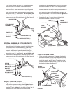
STEP 8 - ATTACH HANDLE
•
Assemble the height adjustment handle to the height
adjustment tube on the front of the sweeper housing.
Use the curved head bolts, bowed washers, lock
washers and hex nuts which come pre-assembled to
the tube. Position the height adjustment handle side to
side so that the height adjustment strap will align up
against the outside of the handle and then
tighten
the
nuts. See fi gure 5.
•
Assemble the grip (T) onto the end of the height
adjustment handle as shown in fi gure 5.
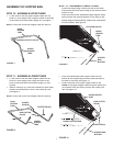
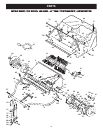
FIGURE 4
STEP 6b - ASSEMBLE HITCH BRACKETS
•
If the tractor hitch is 10" or more above the ground,
place the bent hitch bracket on top of the hitch tubes
and place the hitch bracket assembly underneath
the hitch tubes. Insert two hex bolts (B) through the
brackets, with the rear hex bolt between the cross
bolts in the hitch tubes. Secure the hex bolts (B) with
two nylock nuts (F). See fi gure 4.
Do not tighten yet.
•
Assemble the two spacers (J) onto the hitch pin and
secure the pin with the hairpin cotter (L). See fi gure 4.
NYLOCK NUTS (F)
BENT HITCH
BRACKET
HITCH BRACKET
ASSEMBLY
HEX BOLTS (B)
SPACERS (J)
HAIRPIN
COTTER (L)
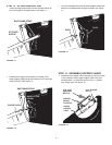
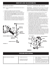
FIGURE 3
NYLOCK NUTS (F)
HITCH BRACKET
ASSEMBLY
BENT HITCH
BRACKET
HEX BOLTS (B)
HAIRPIN COTTER (L)
SPACERS (J)
STEP 6a - ASSEMBLE HITCH BRACKETS
•
If the tractor hitch is less than 10" above the ground,
place the bent hitch bracket underneath the hitch
tubes and place the hitch bracket assembly on top of
the hitch tubes. Insert two hex bolts (B) through the
brackets, with the rear hex bolt between the cross
bolts in the hitch tubes. Secure the hex bolts (B) with
two nylock nuts (F). See fi gure 3.
Do not tighten yet.
•
Assemble the two spacers (J) onto the hitch pin and
secure the pin with the hairpin cotter (L). See fi gure 3.
CURVED
HEAD BOLT
BOWED
WASHER
LOCK
WASHER
HEX NUT
GRIP (T)
HEIGHT
ADJUSTMENT
HANDLE
HEIGHT
ADJUSTMENT
TUBE
HEIGHT
ADJUSTMENT
STRAP