


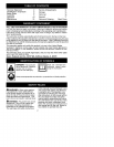
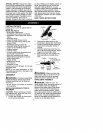

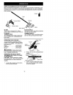
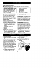
POWERHEAD
END
!Clamp
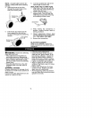
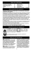
30 inches
I ATTACHMENT
Lower Shoulde •
END
Strap Clamp
o
3. Insert two screws into the screw
holes.
4. Secure shoulder strap clamp by
tightening screws with the hex
wrench.
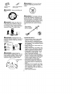
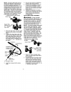
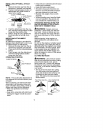
5. Insert your right arm and head
through the shoulder strap and al-
low it to rest on your left shoulder.
Make sure the danger sign is on
your back and the hook is to the
right side of your waist.
NOTE: A one-half twist is built in the
shoulder strap to allow the strap to rest
flat on the shoulder.
6. Adjust the strap, allowing the book
to be about 6 inches below the
waist.
7. Fasten the strap hook to the clamp
and lift the tool to the operating
position.
8. Try on shoulder strap and adjust
for fit and balance before starting
the engine or beginning a cutting
operation.
NOTE: It may be necessary to relo-
cate the shoulder strap clamp on the
shaft for proper balancing of unit.
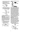
HARNESS
ADJUSTMENT
FOR BALANCE
6 inches
below
waist
4 - 12
inches
above
ground
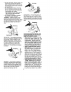
CONFIGURING YOUR UNIT
You can configure your unit using a trim-
mer head for grass and light weeds, or a
weed blade for cutting grass, weeds,
and brush up to 1/2 inch in diameter. To
assemble your unit, go to the section for
the desired configuration and follow the
instructions.
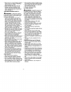
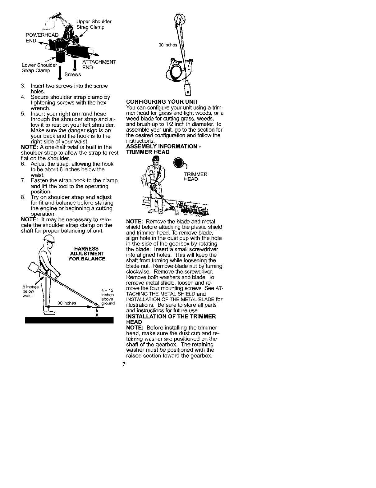
ASSEMBLY INFORMATION -
TRIMMER HEAD
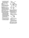
TRIMMER
HEAD
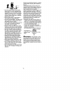
NOTE: Remove the blade and metal
shield before attaching the plastic shield
and trimmer head. To remove blade,
align hole in the dust cup with the hole
in the side of the gearbox by rotating
the blade. Insert a small screwdriver
into aligned holes. This will keep the
shaft from turning while loosening the
blade nut. Remove blade nut by turning
clockwise. Remove the screwdriver.
Remove both washers and blade. To
remove metal shield, loosen and re-
move the four mounting screws. See AT-
TACHINGTHE METALSHIELD and
INSTALLATIONOF THE METAL BLADE for
illustrations. Be sure to store all parts
and instructions for future use.
INSTALLATION OF THE TRIMMER
HEAD
NOTE: Before installing the trimmer
head, make sure the dust cup and re-
taining washer are positioned on the
shaft of the gearbox, The retaining
washer must be positioned with the
raised section toward the gearbox,