


SPECIALNOTICE:Exposuretovibra-
tionsthroughprolongeduseofgasoline
poweredhandtoolscouldcauseblood
vesselornervedamageinthefingers,
hands,andointsofpeoplepronetocir-
cuatondsordersorabnormaswerigs.
Prolongeduseincoldweatherhasbeen
linkedtobloodvesseldamageinother-
wisehealthypeople.Ifsymptomsoccur
suchas numbness, pain, loss of
strength, change in skin color or texture,
or loss of feeling in the fingers, hands, or
joints, discontinue the use of this tool
and seek medical attention. An anti-
vibration system does not guarantee the
avoidance of these problems. Users
who operate power tools on a continual
and regular basis must monitor closely
their physical condition and the condition
of this tool.
SAVE THESE INSTRUCTIONS
CARTON CONTENTS
Check carton contents against the fol-
lowing list.
Model 358.792440
• Brushcutter Attachment
• Handlebar (with Clamp and Knob)
• Handlebar Clamp Base (with Spacer
Tabs)
• Shoulder Strap
• Upper Shoulder Strap Clamp
• Lower Shoulder Strap Clamp (with
Spacer Tabs)
Handlebar Clamp Screws (4)
Shoulder Strap Clamp Screws (2)
Large nut for installing blade
Cupped washer
Trimmer head
4-point weed blade (assembled on
brushcutter attachment)
• Wing nut (screwed onto shield)
• Metal shield (assembled on brush-
cutter attachment)
• Plastic shield
• Attachment Hanger
• Hex Wrench
• Container of line
Examine parts for damage. Do not use
damaged parts.
NOTE: If you need assistance or find
that parts are missing or damaged, call
1-800-235-5878.
ASSEMBLY
=-&
all, WARNING: If received assembled,
repeat all steps to ensure your unit is
properly assembled and all fasteners
are secure.
• A hex wrench (provided) is required
for assembly.
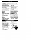
INSTALLING BRUSHCUTTER AT-
TACHMENT
CAUTION: When removing or instal-
ling attachments, place the unit on a
flat surface for stability.
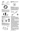
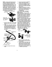
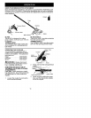
1. Loosen the coupler by turning the
knob counterclockwise.
Coupler
LOOSEN
2,
3.
4.
5.
TIGHTEN Knob
Remove the tube cap from the
brushcutter attachment (if present).
Position locking/release button of
attachment into guide recess of
coupler.
Push the attachment into the cou-
pler until the locking/release button
snaps into the primary hole.
Before using the unit, tighten the
knob securely by turning clock-
wise.
Coupler Primary Hole
\ /Guide Recess
Up!er L°ckin _g/[_
Tube Release Attachment
Button
all}WARNING: Make sure the lock-
ing/release button is locked in the pri-
mary hole and the knob is securely
tightened before operating the unit.
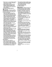
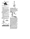
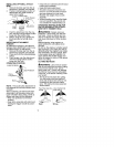
HANDLEBAR ASSEMBLY
DANGER: RISK OF CUT To
avoid serious injury, the barrier portion of
the handlebar must be installed as
shown on the upper tube of the power-
head to provide a barrier between op-
erator and the spinning blade. Attach
tube clamp above arrow on safety warn-
ing decal on the upper tube (powerhead
end of unit). Ensure handlebar is posi-
tioned on handlebar clamp between the
arrows on the handlebar decal.
5