


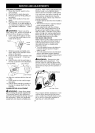

5. Allow unit to run for 5 seconds, then
fully squeeze the throttle trigger to
disengage the starting system (start
lever returns to RUN position).
STARTING A WARM ENGINE
1. Squeeze and hold the throttle trig-
ger.
2. Pull starter rope handle with a con-
trolled and steady motion while
squeezing throttle trigger until en-
gine starts and runs.
NOTE: Normally, the warm starting
procedure can be used within 5-10
minutes after the unit is turned off. If
the unit sits for more than 10 minutes
without being used, it will be neces-
sary to start the unit by following the
steps under STARTING A COLD EN-
GINE or following the starting instruc-
tion steps shown on the unit.
STARTING A FLOODED ENGINE
Flooded engines can be started by
placing the start lever to the RUN posi-
tion. Fully squeeze throttle trigger.
Pull the starter handle repeatedly
while squeezing throttle trigger until
engine starts and runs. This could re-
quire pulling the starter handle many
times, depending on how badly the
unit is flooded.
If the unit still doesn't start, refer to the
TROUBLESHOOTING TABLE or call
1-800-235-5878.
CRAFTSMAN ®
CONVERTIBLE TM FEATURE
This model is equipped with a coupler
which enables optional attachments to
be installed. The optional attachments
are:
Edger ................. 358.79240
Cultivator .............. 358.79241
Blower ................ 358.79242
Brushcutter ............ 358.79244
Pruner ................ 358.79245
&WARNING: Always stop unit
and disconnect spark plug before re-
moving or installing attachments.
REMOVING TRIMMER ATTACH-
MENT (OR OTHER OPTIONAL AT-
TACHMENTS)
CAUTION: When removing or instal-
ling attachments, place the unit on a
flat surface for stability.
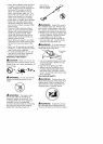
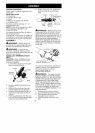
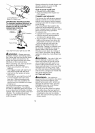
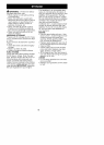
1. Loosen the coupler by turning the
knob counterclockwise.
Upper Shaft
Coupler
Attachment
TIGHTEN Knob
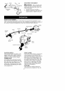
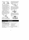
2. Press and hold the locking/release
button.
Locking/Release
Button
/ o
cup er_ Upper Shaft
Attachment
3. While securely holding the engine
and upper shaft, pull the attach-
ment straight out of the coupler.
INSTALLING OPTIONAL ATTACH-
MENTS
1. Remove the shaft cap from the at-
tachment (if present).
2. Position locking/release button of
attachment into guide recess of
coupler.
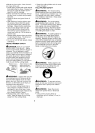
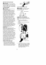
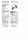
3. Push the attachment into the cou-
pler until the locking/release button
snaps into the primary hole.
4. Before using the unit, tighten the
knob securely by turning clock-
wise.
Coupler Primary Hole
Guide Recess
Upper Locking/ Attachment
Shaft Release
Button
,'_WARNING: Make sure the lock-
ing/release button is locked in the pri-
mary hole and the knob is securely
tightened before operating the unit. All
attachments are designed to be used in
the primary hole unless otherwise
stated in the applicable attachment op-
erator's manual. Using the wrong hole
could lead to serious injury or damage
to the unit.
13