


7
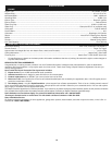
AIR FILTER MAINTENANCE
The condition of the air filter is important
to the operation of the unit. A dirty air
filter will restrict air flow and change the
air/fuel mixture. This is often mistaken
for an out of adjustment carburetor.
Check the condition of the air filter
before adjusting the idle speed screw.
Refer to Air Filter Maintenance.
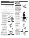
Removing the Air Filter/Muffler
Cover
1. Remove the four (4) screws
securing the air filter/ muffler
cover (Fig. 14). Use a flat blade
or T20 Torx bit screwdriver.
2. Pull the cover from the
engine. Do not force.
Cleaning the Air Filter
Failure to maintain your air
filter properly can result in
poor performance or can
cause permanent damage to
your engine.
1. Remove air filter/muffler
cover. Refer to Removing
the Air Filter/Muffler
Cover above.
2.
Turn cover over and look
inside to locate the air filter.
Remove the air filter from
inside the air filter/muffler
cover (Fig. 15).
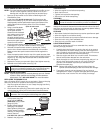
3. Wash the filter in detergent
and water (Fig. 16). Rinse
the filter thoroughly.
Squeeze out excess water.
Allow it to dry completely.
4. Apply enough clean SAE
30 oil to lightly coat the
filter (Fig. 17).
5. Squeeze the filter to
spread and remove
excess oil (Fig. 18).
6. Replace the air filter
inside the air filter/muffler
cover (Fig. 15).
NOTE: Operating the unit
without the air filter
and air filter/muffler
cover assembly will
VOID the warranty.
Reinstalling the Air
Filter/Muffler Cover
1. Place the air filter/muffler
cover over the back of the
carburetor and muffler.
Align the screw holes.
2. Insert the four (4) screws
into the holes in the air
filter/muffler cover (Fig.
14) and tighten. Do not
over tighten.
MAINTENANCE & REPAIR INSTRUCTIONS
WARNING:
To avoid
serious personal injury,
always turn your unit off
and allow it to cool before
you clean or service it.
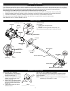
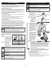
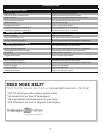
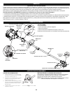
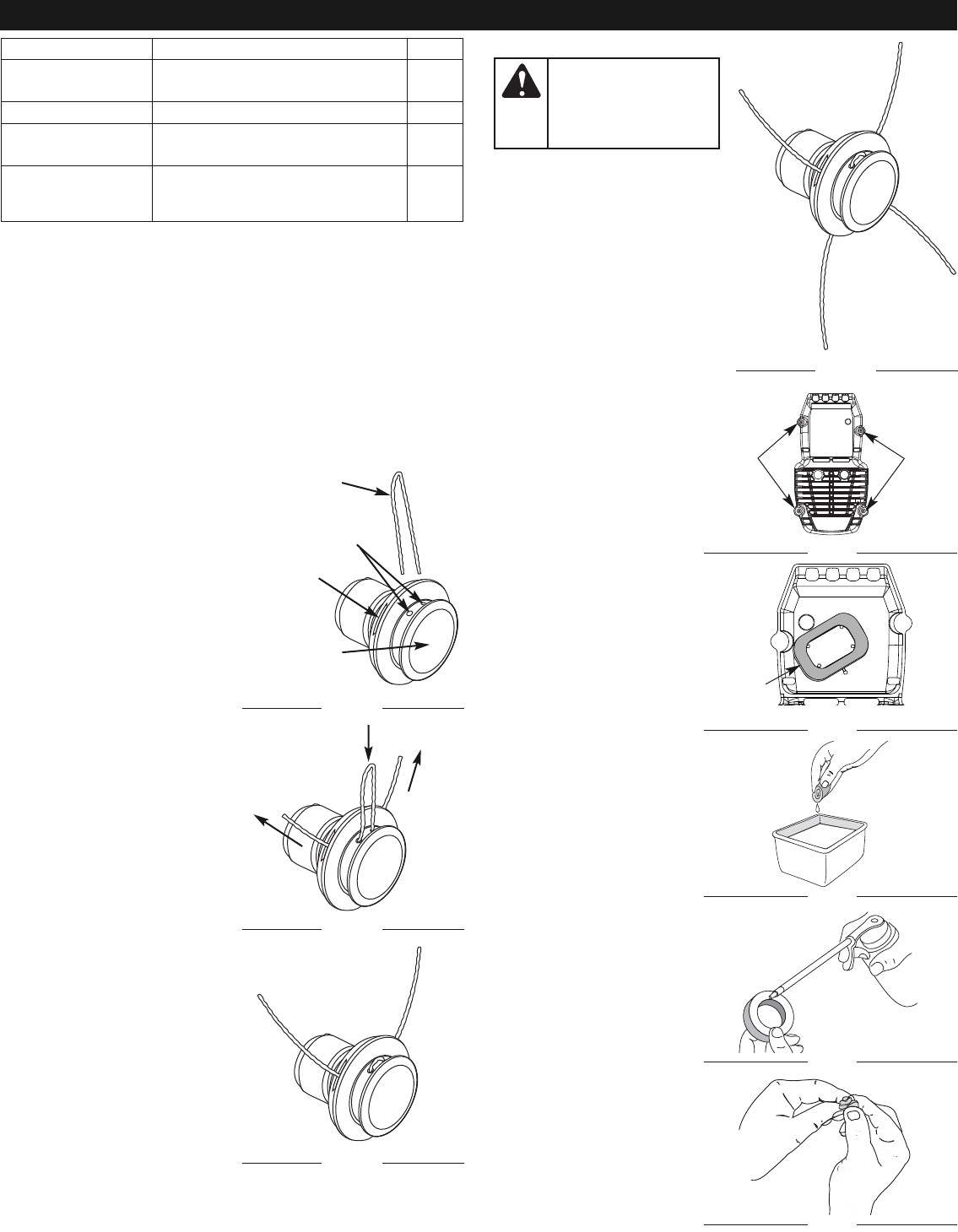
LINE REPLACEMENT
for Hassle-Free™ Plus Cutting Head
Always use Craftsman Hassle-Free™ XTRA QUIET Spiral Line.
Choose the line size best suited for the job at hand. Red colored line
is designed for cutting grass and small weeds. Black colored line is
designed for cutting larger weeds and light brush.
NOTE: Before inserting new line into the holes in the cutting head,
identify the proper holes. Follow directions as shown on the
glide plate. Do Not attempt to remove the cutting head from
the unit when replacing line.
NOTE: Do not mix lines. Use 2 black or 2 red only.
1. Remove the old line and line glide plate from the cutting head.
2. Clean entire surface of cutting head.
3. Reinstall line glide plate (Fig. 10).
The glide plate is a keyed item
and will only fit one way. If it does
not go into the cutting head
smoothly, DO NOT force it.
Rotate the glide plate until it
slides into the cutting head easily.
NOTE: The glide plate must be
installed in the cutting head
before inserting new line.
4. Insert both ends of your line
through the insertion holes in the
side of the cutting head (Fig. 10).
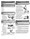
5.
Push and/or pull the line so that
the line is snug against the hub
and is fully extended through the
positioning tunnels (Fig. 11).
6. Correctly installed line will be
the same length on both sides
(Fig. 12).
NOTE: Make sure that when
installing new line, that the
line is as close to even as
possible. Any variation in
lengths may cause the unit
to vibrate excessively. If this
happens, stop the unit and
make sure the line is even.
7. Repeat steps 4 thru 6 to install
the second trimmer line.
8. Correctly installed, the four
lines will all be the same
length (Fig. 13).
Some line breakage will occur from:
• Entanglement with foreign matter
• Normal line fatigue
• Attempting to cut thick, stalky
weeds
• Forcing the line into objects
such as walls or fence posts
NOTE: During normal use the
trimming line may become worn unevenly which may cause
excessive vibrations in the unit. If this becomes
uncomfortable or uncontrollable, stop the unit and replace
the line. Refer to the Line Replacement instructions above.
FREQUENCY MAINTENANCE REQUIRED SEE
Before starting
engine
Fill fuel tank with fresh fuel p. 5
Every 10 hours Clean and re-oil air filter p. 7
Every 25 hours Check and clean spark arrestor
Check spark plug condition and gap
p. 8
p. 8
Every 50 hours Inspect exhaust port and spark
arrestor screen for clogging or
obstruction
p. 8
Screws
Fig. 14
Screws
Air Filter
Fig. 15
Fig. 16
Fig. 17
Fig. 18
Inside Muffler C over
Positioning
Tunnel
Trimming
Line
Fig. 10
Insertion
Holes
Glide Plate
Fig. 11
Fig. 12
Fig. 13