


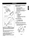
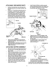
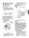
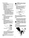
ATTACHING DISCHARGE CHUTE
• Remove the wing knobs from each side of the
discharge opening on the chipper-shredder. See
figure 3.
• Using two 7/16" wrenches, remove hex lock nut,
two spacers, and the hex bolt from top of the
housing assembly. For easy assembly, do not
remove the second spacer from the hex bolt.
• Place the discharge chute in position on the
discharge opening. Insert hex bolt and spacer
through hinge on discharge chute and housing
(spacer fits inside of hinge). See figure 3 inset.
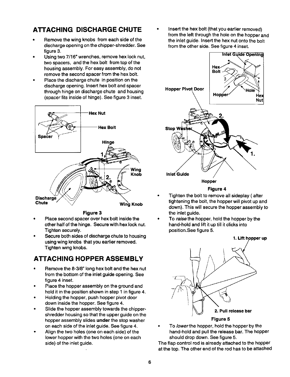
Insert the hex bolt (that you earlier removed)
from the left through the hole on the hopper and
the inlet guide. Insert the hex nut onto the bolt
from the other side. See figure 4 inset.
Hopper Pivot Door
Inlet G_
Nu1
Hex Nut
-- Hex Bolt
Hinge
Sto:
Wing
Knob
Discharge
Chute
tg Knob
Figure 3
Place second spacer over hex bolt inside the
other half ofthe hinge. Secure with hex lock nut.
Tighten securely.
Secure both sides of discharge chute to housing
using wing knobs that you earlier removed.
Tighten wing knobs.
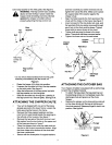
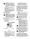
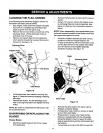
ATTACHING HOPPER ASSEMBLY
• Remove the 8-3/8" long hex bolt and the hex nut
from the bottom of the inlet guide opening. See
figure 4 inset.
• Place the hopper assembly on the ground and
hold itin the position shown in step 1 in figure 4.
• Holding the hopper, push hopper pivot door
down inside the hopper. See figure 4.
• Slide the hopper assembly towards the chipper-
shredder housing so that the upper guide on the
hopper assembly slides under the stop washer
on each side of the inlet guide. See figure 4.
• Align the two holes (one on each side) of the
lower hopper with the two holes (one on each
side) ofthe inlet guide.
Inlet Guide
Hopper
Figure 4
Tighten the bolt to remove all sideplay ( after
tightening the bolt, the hopper willpivot up and
down). This will secure the hopper assembly to
the inletguide.
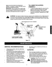
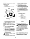
To raise the hopper, hold the hopper by the
hand-hold and lift itup till itclicks into
position.See figure 5.
1. Lift
2. Pull release bar
Figure 5
• To Iowerthe hopper, hold the hopper by the
hand-hold and pull the release bar. The hopper
should drop down. See figure 5.
The flap control rod is already attached to the hopper
at the top. The other end of the rod has to be attached
6