


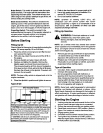
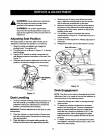
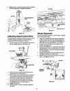
4. Retighten jam nuts when proper tension is reached.
Test the adjustment. Readjust ifnecessary.
Jam Nut
Jam Nut
Deck Engagement
............ Cable
/
/
/
Figure 19
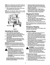
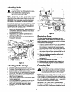
Adjusting Speed Control Rod
This adjustment is necessary when the vehicle cannot
hold the full range of speeds, orshows belt drag
(=creep")when the drive pedal is released.
1. Remove hairpin clip secudng speed control rod to
the drive pedal assembly. See Figure 20.
DrivePedal
\
Control
Rod
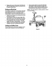
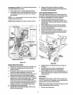
Figure 21
Adjust this ferrule
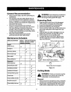
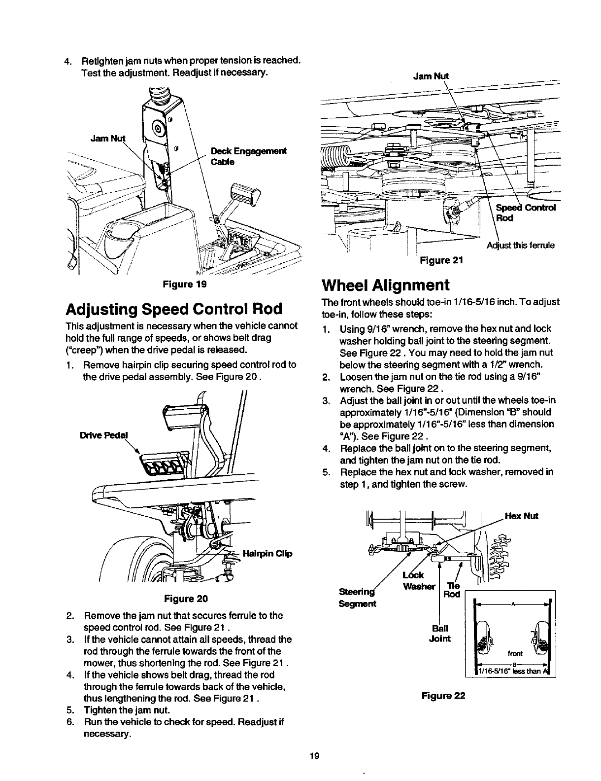
Wheel Alignment
The front wheels should toe-in 1/16-5/16 inch. To adjust
toe-in, follow these steps:
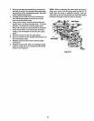
1. Using 9/16" wrench, remove the hex nut and lock
washer holding ball jointto the steedng segment.
See Figure 22. You may need to hold the jam nut
below the steering segment with a 1/2" wrench.
2. Loosen the jam nut on the tie red using a 9/16"
wrench. See Figure 22.
3. Adjust the balljoint in or out untilthe wheels toe-in
approximately 1/16"-5/16" (Dimension =B"should
be approximately 1/16"-5/16" less than dimension
=A").See Figure 22.
4. Replace the balljoint on to the steering segment,
and tighten the jam nut on the tie rod.
5. Replace the hex nut and lock washer, removed in
step 1, and tighten the screw.
Hex Nut
- Hairpin Clip
Figure 20
2. Remove the jam nut that secures ferrule to the
speed control rod. See Figure 21.
3. Ifthe vehicle cannot attain all speeds, thread the
rodthrough the ferrule towards the front of the
mower, thus shortening the rod. See Figure 21.
4. Ifthe vehicle shows belt drag, thread the rod
through the ferrule towards back of the vehicle,
thus lengthening the rod. See Figure 21.
5. Tighten the jam nut.
6. Run the vehicle to check for speed. Readjust if
necessary.
Segment
Waeher
Rod
Ball
Joint
Figure 22
1/16-5/16"lessthan/
19