


WARNING: Never attempt any adjustment
whilethe engine is running, except where
specified in the operator's manual.
WARNING: For all other adjustments,
disconnect the spark plug wire(s) and ground
against the engine first. Then proceed with the
adjustment.
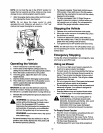
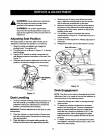
Adjusting Seat Position
The seat position on the lawn utilityvehicle can be
adjusted to maximize the operator's convenience.
1. Stop the vehicle completely and engage the
parking brake. Tum ignition off.
2. Pivot the seat up, as shown inFigure 17, to access
seat hardware.
3. Using a 9/16" wrench or socket, loosen the four
self-tapping screws on the bottom ofthe seat. See
Figure 17.
4. Slide the seat forward or backward inthe slot,and
position itas desired. Retighten the four screws.
Figure 17
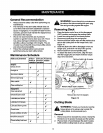
Deck Levelling
1. In case of uneven mowing, check air pressure in all
four tires and fillup ifneeded. Recommended air
pressure is20-22 psi. Ifthis does not correct the
problem, proceed with deck levelling.
IMPORTANT:Perform adjustments to the deck on a fiat,
level surface.
2. Place the vehicle on a level surface. Depress and
lock the parking brake. Disconnect the spark plug
wire and ground it.
3. Place the deck inthe lowest cutting position by
sliding the deck leverto the appropriate position.
4. Wearing a pair of heavy work gloves to prevent
injury, rotate the cutting blade sothat it ispointed
side to side and perpendicular to the dder.
5. Measure the distance from each tip of the blade to
the ground, If the distance from both blade tips to
the ground isnot the same, perform a side to side
levelling ofthe deck.
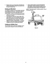
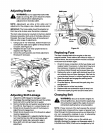
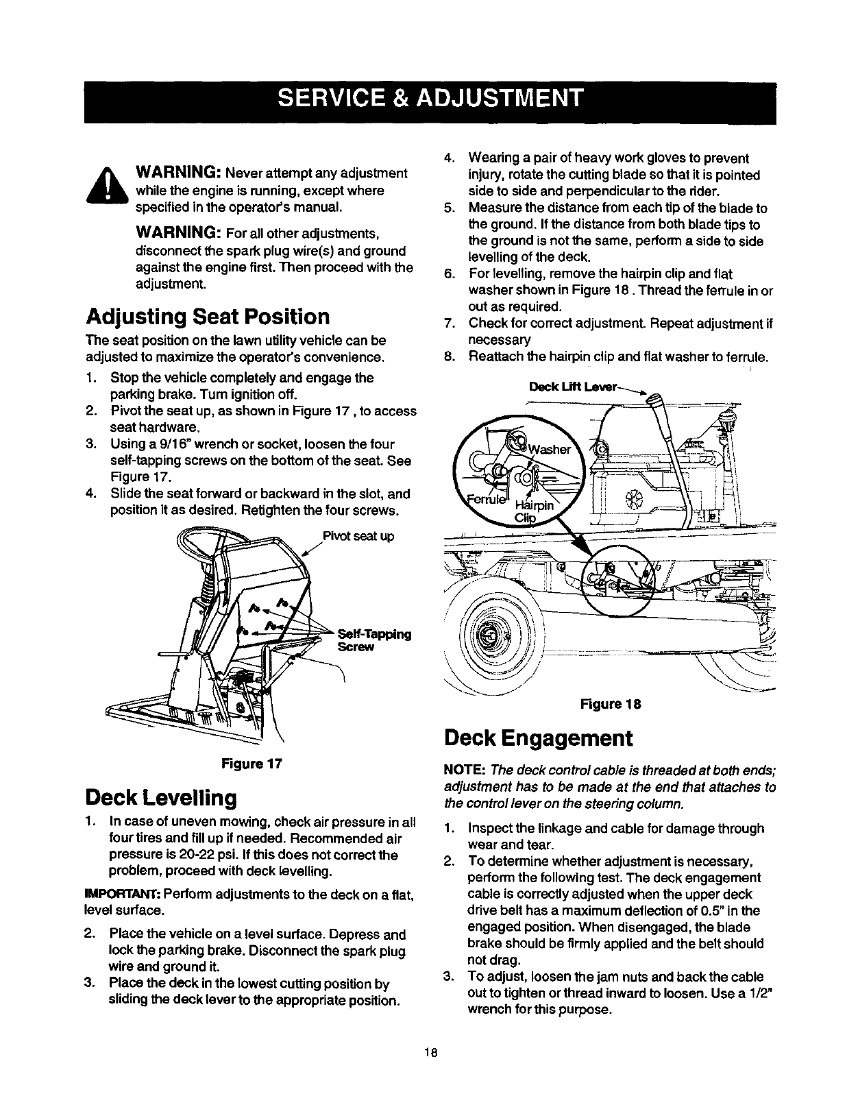
6. For levelling, remove the hairpin clipand flat
washer shown in Figure 18. Thread the ferrule in or
out as required.
7. Check for correct adjustment. Repeat adjustment if
necessary
8. Reattach the hairpin clip and flat washer to ferrule.
Deck Lift Lever-_._ _ --_-
== • i !1
Ciip_ _ -_-__I.....
/[ I _ --- i.,r
,, \W%,,,,,,,,,_/// ,.................. _-,-__.
Figure 18
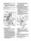
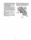
Deck Engagement
NOTE: Thedeck control cable is threaded at both ends;
adjustment has to be made at the end that attaches to
the controllever on the steering column.
1. Inspect the linkage and cable for damage through
wear and tear.
2. To determine whether adjustment isnecessary,
perform the following test. The deck engagement
cable is correctly adjusted when the upper deck
drive belt has a maximum deflection of 0.5" inthe
engaged position.When disengaged, the blade
brake should be firmly applied and the beltshould
not drag.
3. To adjust, loosen the jam nuts and back the cable
out totighten or thread inwardto loosen. Use a 1/2"
wrench for this purpose.
18