


14 DR
®
ROTO-HOG™ POWER TILLER
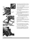
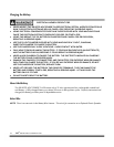
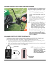
5. Place the Battery in the Battery Bracket and secure it
using the Battery Bar with two (2) 1/4" x 7-1/2" Bolts
and 1/4" Lock Nuts from the Hardware Bag using
two (2)
7/16" Wrenches (Figure 4).
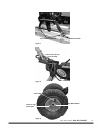
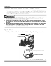
6. Using a 1/2" Wrench or Socket, remove the three (3)
screws securing the SMOOTH-TRAK™ Hitch to the
shipping pallet (Figure 5).
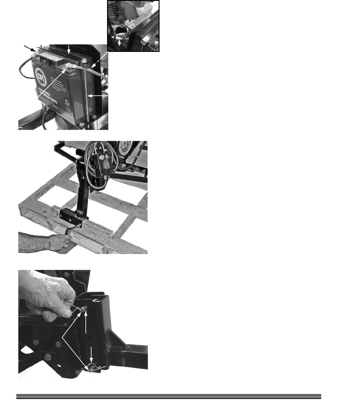
7. Using the two (2) 4" Pins and Bow-Tie Cotter Pins
from the Hardware Bag, attach the Tow Hitch to the
machine (Figure 6).
8. Using a 1/2" Wrench, remove the four (4) Bolts from
the Axle Hold-Down Brackets at the rear of the
shipping pallet (Figure 7 on page 15) and remove the
Bracket from each Axle.
NOTE: At this point, you will have two (2) Screws from the
Hitch, four (4) Screws from the Axle Brackets, and
the two (2) Axle Brackets. All this hardware was for
shipping and is NOT required for assembly.
9. Using two
(2) 5/16" Wrenches, attach the Battery
Cables to the Battery (Figure 4).
10. Using the Control Box (Figure 8 on page 15), lower
the Tines all the way down, which will raise the Wheel
Axles from the pallet.
11. Slide a Wheel onto each Axle making sure that the
Wheel Valve Stem is to the outside (Figure 9 on page
15).
12. From the Hardware Bag, place one (1) Flat Wheel
Washer on each Axle, slide a Cotter Pin through the
Hole in the Axle on each side, and spread the Cotter
Pin Legs using Pliers (Figure 9 on page 15).
13. Raise the Tines, lowering the Wheels, and roll the
machine from the shipping pallet. Do not discard
your packaging material until you are fully satisfied
with your new DR ROTO-HOG POWER TILLER.
Figure 5
Battery Bar
1/4" x 7-1/2 Bolts
(2 places)
Figure 4
Negative
Terminal
Positive
Terminal
Figure 6
Bow Tie
Cotter Pins
4" Pins
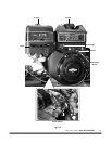
Fuses
Fuse Location in
Front of Battery