


• Reorient or relocate the receiving antenna.
• Increase the separation between the equipment and receiver.
• Connect the equipment into an outlet on a circuit different from that to
which the receiver is connected.
• Consult the dealer or an experienced radio/TV technician for help.
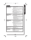
• Fixture must be connected to a 120 Volt, 60 Hz 2.5, 300 watt power source. Any
other connection voids warranty.
• This motion activated twin floodlight should be installed by persons with experi-
ence in household wiring or by a qualified electrician. The electrical system, and
the method of electrically connecting the fixture to it, must be in accordance with
the National Electrical Code and local building codes.
• For proper operation and protection against damage, the motion sensor head
adjustment knobs must be facing the ground.
• Disassembly of your fixture will void the warranty.
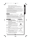
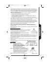
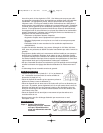
For best results
• Install your fixture 8-12 feet above ground (motion detector is
less sensitive above 12 feet).
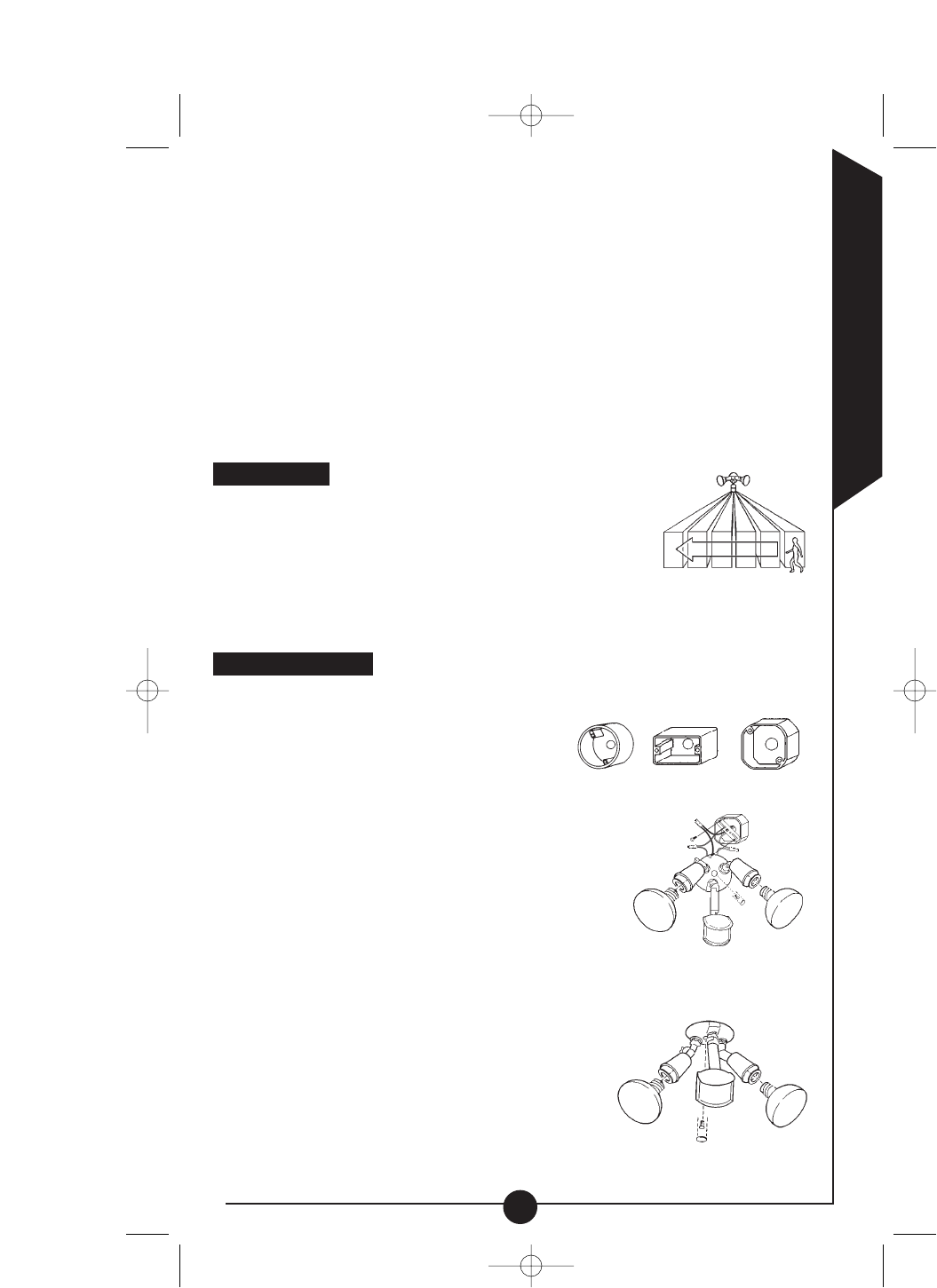
• Locate fixture so motion moves across detection zone (J).
• Locate fixture away from heat producing sources to prevent
false triggering. Also be very careful not to include objects
such as windows, white walls and water in the detection zone whenever possible.
• Locate fixture away from moving objects such as trees and street traffic.
• Do not install more than one motion activated floodlight on one wall switch.
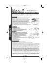
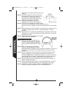
Mounting your fixture
Step 1: Turn off the power at the main
fuse/breaker box. Check to make
sure power has been disconnected
before continuing.
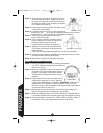
Step 2: Line up the holes on the mounting brack-
et with the holes on your junction box.
Using either (2) #6 screws or (2) #8
screws (depending on size of the holes in your
junction box), attach the mounting bracket to your
junction box (K).
Step 3: Thread fixture wires through coverplate gasket.
Step 4: Connect black wire to house black wire and con-
nect white wire to house white wire using wire
nuts provided.
Step 5: Attach fixture to the junction box with two screws
provided.
Step 6: Attach fixture to the mounting bracket using the center bolt provided.
Insert plastic color matched plug in center bolt hole for finished appear-
ance.
Step 7: Apply silicone caulking around edges of coverplate
and in any open holes to provide a watertight
seal from rain and moisture.
Step 8: Insert gaskets into lampholder assembly, tight-
ly against lampholder and screw bulbs into
each lampholder. (Do not overtighten bulbs).
Step 9: Turn power on at main fuse/breaker box.
ENGLISH
3
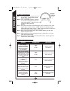
J
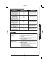
Round Rectangular (horizontal) Octagonal
Your fixture mounts
to the following standard
junction boxes:
K
(eave mount)
(wall mount)
MS185,MS185W I.S. 325-1417 1/7/04 3:59 PM Page 3