


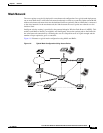

1-6
Cisco Aironet 1520 Series Outdoor Mesh Access Point Hardware Installation Guide
OL-12632-03
Chapter 1 Overview
Hardware Features
Some of the access point’s hardware features are listed below:
• Multiple radios (2.4-GHz, 5-GHz, and 4.9-GHz)—see the “Multiple Radio Operation” section on
page 1-6
• External radio antennas—see the “External Antennas” section on page 1-7
• Multiple power sources—see the “Multiple Power Sources” section on page 1-8
• Ethernet ports—see the “Ethernet Ports” section on page 1-9
• Rugged metal enclosure—see the “Metal Enclosure” section on page 1-10
• Optional cable modem—see the “Cable Modem” section on page 1-10
• Optional hardware—see the “Optional Hardware” section on page 1-10
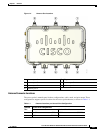
Connectors
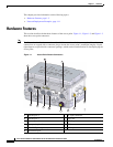
The optional features of the access point support these connectors (see Figure 1-1):
• PoE-in connector—internal RJ-45 with liquid tight adapter for waterproofing
• PoE-out connector—internal RJ-45 with liquid tight adapter for waterproofing
• Three, four, or six antenna connectors (Type N)—depends on access point configuration
• Fiber-optic connector—internal small form-factor pluggable (SFP) transceiver with LC connector
• Power-over-cable (POC) stinger connector—customer provided
• AC power connector (3-pin Remke Mini-Link 50908)
• DC power connector—internal 2-pin connector
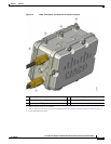
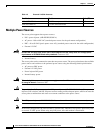
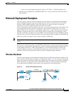
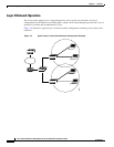
Multiple Radio Operation
The access point supports 2.4-GHz and 5-GHz radios using external antennas (see “External Antennas”).
The LAP1522 model supports simultaneous dual-radio operation using a 2.4-GHz 802.11b/g radio and
a 5-GHz 802.11a radio.The 5-GHz radio can operate in either the upper industrial, scientific and medical
(ISM) 5.8-GHz band or the public safety 4.9-GHz band. The 5-GHz radio supports one antenna and is
used for backhaul operations to the controller.
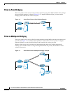
3 2.4-GHz antenna connector
(TX/RX)
2.4-GHz antenna connector (RX)
4–
1
2.4-GHz antenna connector (RX)
5–
1
–
1
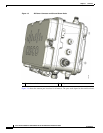
6–
1
2.4-GHz antenna connector
(TX/RX)
1. Reserved for future use.
Table 1-1 Antenna Locations per Access Point Configuration (continued)
Antenna
Port
Access Point Configurations
Cable Mesh and Pole Mount