


1-3
Cisco Aironet 1520 Series Outdoor Mesh Access Point Hardware Installation Guide
OL-12632-03
Chapter 1 Overview
Hardware Features
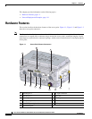
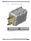
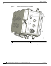
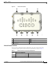
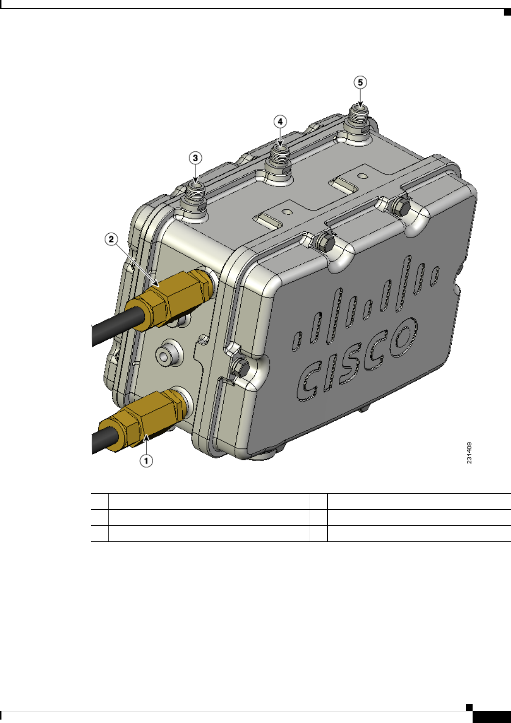
Figure 1-2 Cable, Fiber-Optic, and Antenna Connector Locations
1 Cable POC connector (optional)
1
1. Stinger connector shown is user supplied.
4 Antenna port 2
2
(Type N)
2. Antenna locations depend upon access point configuration (see the “Antenna Connector Locations” section on page 1-5).
2 Fiber-optic connector
3
(optional)
3. Liquid tight adapter not shown.
5 Antenna port 1
2
(Type N)
3 Antenna port 3
2
(Type N)