


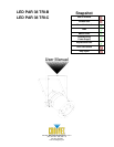
LED PAR 38-Tri B&C User Manual 9 Rev. 2
Fixture Linking
You will need a serial data link to run light shows of one or more fixtures using a DMX controller or to
run synchronized shows on two or more fixtures set to a master/slave operating mode. The combined
number of channels required by all the fixtures on a serial data link determines the number of fixtures
the data link can support.
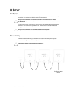
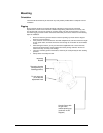
Fixtures on a serial data link must be daisy chained in one single line. To comply with the EIA-
485 standard, no more than 32 fixtures should be connected on one data link. Connecting
more than 32 fixtures on one serial data link without the use of a DMX optically-isolated
splitter may result in deterioration of the digital DMX signal.
Maximum recommended serial data link distance: 500 m (1640 ft)
Maximum recommended number of fixtures on a serial data link: 32
Data Cabling
To link fixtures together you must obtain data cables. You can purchase CHAUVET certified DMX
cables directly from a dealer/distributor or construct your own cable. If you choose to create your own
cable please use data-grade cables that can carry a high quality signal and are less prone to
electromagnetic interference.
4. OPERATING INSTRUCTIONS
Configuring the Starting Address
Each fixture requires a starting address from 1~512. A fixture requiring one or more channels for
control begins to read the data on the channel indicated by the starting address. For example, a
fixture that uses seven DMX channels and is addressed to start on DMX channel 100, will read data
from channels: 100, 101, 102, 103, 104, 105 and 106. Choose the starting addresses for each fixture
so that the channels used do not overlap. In addition, you should note the starting address selected
for future reference.
The LED PAR 38 Tri-B/C
fixture uses seven or three DMX channels. If this is your first time using
DMX, we recommend reading the “DMX Primer” section in the “Appendix”.
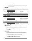
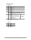
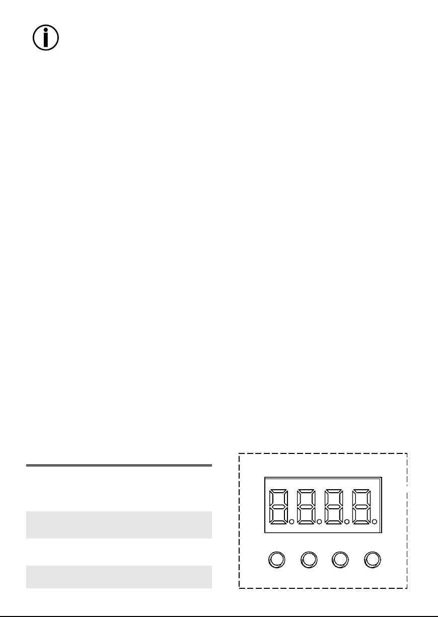
Control Panel Functions
Access control panel functions using the four buttons located directly underneath the LED display on
the included wired remote.
BUTTON
FUNCTION
<MENU>
Used to scroll through the
current operating mode,
as well as back out of the
current menu option
<DOWN>
Used to select decreasing
advancement in the value
<UP>
Used to select increasing
advancement in the value
<ENTER>
Used to select a value and
store it to memory