


15
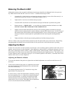
For Advanced GT users, it may be helpful to remove the front latitude adjustment screw completely. This will allow
the mount to reach lower latitudes without the screw coming into contact with the R.A. motor assembly. To remove
the latitude screw, first use the rear screw to raise the mount head all the way up. Then remove the front latitude
screw completely. Now you should be able to manually move the mount head all the way to its lowest latitude. Now,
using only the rear screw, raise the mount to your desired latitude.
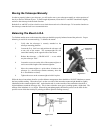
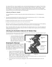
Adjusting the Mount in Azimuth
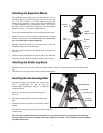
For rough adjustments in azimuth, simply pick up the telescope and tripod and move it. For fine adjustments in
azimuth:
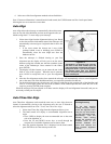
1. Turn the azimuth adjustment knobs located on either side of the azimuth housing (see Fig 2-14). While standing
behind the telescope, the knobs are on the front of the mount.
• Turning the right adjustment knob clockwise moves the mount toward the right.
• Turning the left adjustment knob clockwise moves the mount to the left.
Both screws push off of the peg on the tripod head, which means you may have to loosen one screw while tightening
the other. The screw that holds the equatorial mount to the tripod may have to be loosened slightly.
Keep in mind that adjusting the mount is done during the polar alignment process only. Once polar aligned, the
mount must NOT be moved. Pointing the telescope is done by moving the mount in right ascension and declination,
as described earlier in this manual.
A
A
t
t
t
t
a
a
c
c
h
h
i
i
n
n
g
g
t
t
h
h
e
e
D
D
e
e
c
c
l
l
i
i
n
n
a
a
t
t
i
i
o
o
n
n
C
C
a
a
b
b
l
l
e
e
(
(
F
F
o
o
r
r
G
G
T
T
M
M
o
o
d
d
e
e
l
l
s
s
O
O
n
n
l
l
y
y
)
)
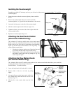
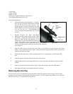
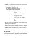
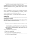
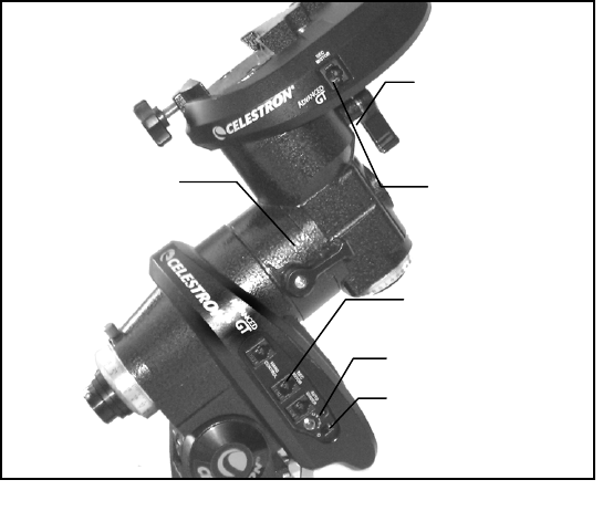
The Advanced Series mount comes with a declination cable that connects from the R.A. motor drive electronic panel
to the Dec motor drive. To attach the motor cable:
• Locate the Declination cable and plug
one end of the cable into the port on
the electronics panel labeled DEC
Port and plug the other end of the
cable into the port located on the
declination motor drive (see Fig 2-15).
P
P
o
o
w
w
e
e
r
r
i
i
n
n
g
g
t
t
h
h
e
e
T
T
e
e
l
l
e
e
s
s
c
c
o
o
p
p
e
e
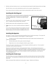
The Advanced GT can be powered by the supplied
car battery adapter or optional 12v AC adapter. Use
only adapters supplied by Celestron. Using any
other adapter may damage the electronics or cause
the telescope not to operate properly, and will void
your manufacturer's warranty.
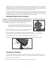
1. To power the telescope with the car battery
adapter (or 12v AC adapter), simply plug
the round post into the 12v outlet on the
electronic panel and plug the other end into your cars cigarette
lighter outlet or portable power supply (see Optional
Accessories). Note: to prevent the power cord from being accidentally pulled out, wrap the power cord
around the strain relief located below the power switch.
2. Turn on the power to the telescope by flipping the switch, located on the electronics panel, to the "On"
position.
Declination Cable
Output Port
Declination Cable
Input Port
12v Power Input
On/Off Switch
Figure 2-15
DEC Locking
Clamp
R.A. Lockin
g
Clam
p