


8
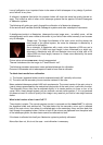
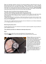
In the lower sketch the left side screw is threaded into the mirror support plate and will pull that
side down, the right hand screw has it’s thread cut into the bottom plate and would lift the mirror
up.
The spring loaded mirror support is easier to manufacture and to work with. On the other hand the
resilience of the springs can change with temperature and age, resulting in frequent loss of colli-
mation of the main mirror. Therefore springs are used only in smaller Newtonian telescopes. Ad-
justment by push/pull screws are a little more costly to produce and more elaborate to work with
but they guarantee practically no movement of the main mirror’s adjustments due to knocks and
vibrations (transport). They are therefore mainly used in larger telescope systems with the larger
weight of the main mirror.
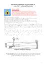
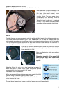
Adjustment of the main mirror is done best by two persons. While you are turning the main mirror’s
adjustment screws your friend would be reporting about the movement of the reflected laser light
beam.
Case 1:
The main mirror of your Newtonian may be out of adjustment quite a bit.
This may result in no success in step 1 above, i.e. you don’t see the reflected laser beam on the
reference plane at all. In this case cautiously glance through the grid towards the secondary mirror.
With a little bit of luck you will see somewhere at the inner walls of the eyepiece holder the grazing
reflection of the laser beam. If you see it, adjust the main mirror first to bring the laser beam’s light
point onto the grid – continue the adjusting operation until the beam is centered on the grid, show-
ing full collimation.
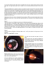
Case 2:
You don’t see any reflection of the laser beam at all – well, your system is a long way out of ad-
justment.
Again your Laser-Colli™ can help.
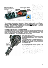
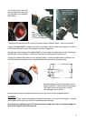
First look into the tube front down to the pri-
mary.
On the main mirror you see the reflection of
the secondary mirror and the reference grid. In
the grid plane itself you see many reflected
images of the laser dot.
If these reflected images are not orientated in
a straight line but spread, as in the picture left,
you have to adjust the main mirror in such a
way to line them up in a straight line (see pic-
ture below).
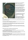
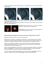
Picture above again shows the view from the
tube’s front to the reflected images of the secon-
dary mirror and the grid plane.
If the red reflections are exactly orientated in a
line the main mirror is well adjusted already
(white line shown in the picture serves only for
clarification).