


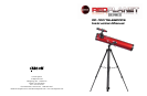
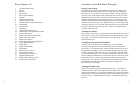
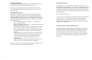
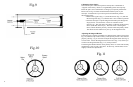
Key to Figures 1-8:
1. 10x30mmFinderScope
2. Focuser
3. Eyepiece
4. Focus Knobs
5. Optical Tube Assembly
6. UMount
7. Horizontal Lock Knob
8. UMountLockingScrew
9. AltitudeRodFineAdjustmentControl
10. Altitude Rod
11. Locking Plates
12. Tripod Legs
13. Locking Plate Thumbscrews
14. AltitudeRodCoarseAdjustmentControl
15. Focuser Thumbscrew
16. FinderScopeBracketThumbscrew
17. FinderScopeFocusKnob
18. FinderScopeBracket
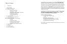
19. FinderScopeBracketMountingBolts
20. Tripod Tightening Ring
21. Tripod Brace
22. EyepieceHolderSlots
23. Tripod Hook
24. Tripod Leg Lock Closed
25. Tripod Leg Lock Open
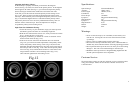
26. DiagonalMirrorTiltScrews
27. DiagonalMirrorHolder
28. PrimaryMirrorLockingScrews
29. PrimaryMirrorTiltScrews
Assembly of your Red Planet Telescope:
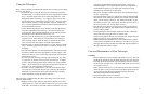
Setting Up Your Tripod:
The aluminum tripod comes preassembled and ready-to-use. Remove the
tripod from the box and pull apart the legs. Gently push down the tripod
braces(Fig.6-21)untiltheyareinthelowestposition.Turnthetightening
ring(Fig.6-20)(locatedatthecenterofthetripodbrace)clockwisetolock
the tripod in the open position. You can then extend the legs to the desired
heightbypullingopenthetaboneachleglock(Fig.6-25),slidingtheleg
down the desired amount and then pushing the leg lock back against the leg
intothelockedposition(Fig.6-24).Repeattheprocesswitheachlegtrying
to keep the tripod as level as possible with the ground. You will notice there
areholesinthetripodlegbraces(Fig.6-22).Thesearedesignedtohold
eyepieces when not in use.
Attaching the U Mount:
RemovetheUmount(Fig.1-6)fromthebox.Placethebottomofthemount
into the hole in the top of the tripod head and secure with the mount locking
screw(Fig.1-8).Pleasebecarefultomakesurethatthemountissecurely
attached to the tripod.
Attaching the Telescope Tube to the Mount:
Carefullyremovetheopticaltubeassembly(Fig.1-5)fromthebox.
GentlyplacetheopticaltubebetweentheforksoftheUmountwiththe
focuser(Fig.1-2)towardsthefront.Slidetheknobslocatedonthesidesof
the optical tube assembly into the corresponding openings at the top of the
Umount.Twistthelockingplates(Fig.3-11)onthesidesofthetelescope
untilthethumbscrew(Fig.3-13)isalignedwiththeholesontheforksofthe
mount.Tightenthethumbscrewstosecurethetelescopetothemount.Slide
thealtituderod(Fig.3-10)intotheholeinthealtitudecoarseadjustment
control(Fig.3-14).Aligntheendofthealtituderodwiththecorresponding
threaded hole on the telescope and secure using the included screw.
Be careful not to over-tighten.
Attaching the Finder Scope:
Therearetwonderscopebracketmountingbolts(Fig.5-19)locatedat
the front end of the optical tube. Remove the nuts and set aside. Place the
nderscopebracket(Fig.5-18)ontothemountingbolts,replacethenutsand
tightendownsecurelytotheopticaltube.Makesurethebracketisoriented
asshowninFig.5.Slidethenderscope(Fig.1-1)intothebracketfacing
forward.
98