


LTR20091024, Rev. A
20
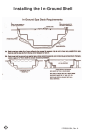
NOTE: Once complete, water test the plumbing run for at least three
days prior to covering any plumbing trenches and back-lling spa cavity
completely.
NOTE: Some local inspectors require pressure testing the plumbing lines.
Although the spa is pressure tested at the factory, local inspectors may
insist on pressure testing the plumbing run between the spa and equip-
ment pack.
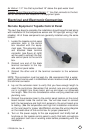
Gate/Slice Valves
The use of gate valves is recommended on all plumbing lines (both suction
and return lines). These valves are used to contain the spa’s water in ei-
ther the equipment or the spa. This will assist in the pump priming process
and future servicing without needing to drain the spa.
NOTE: When draining the spa to perform maintenance, always close the
gate valves prior to draining. This will maintain the pumps prime.
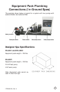
Connecting Plumbing to Remote Equipment
Connecting the plumbing from the spa to the equipment pack must be
performed in accordance to local and city codes.
NOTE: Most codes require plumbing to be rigid PVC schedule 40 or heavier
in both above and below ground installations. In most cases, the use of
exible PVC plumbing is acceptable when properly buried in trenches.
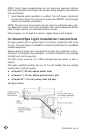
Most water plumbing lines are 2” or larger and must be schedule 40 or
heavier PVC. When plumbing, minimize the use of 90˚ elbows as much as
possible. The use of 45 ˚ elbows will increase the amount of jet pressure
you will have over the use of 90˚ elbows.
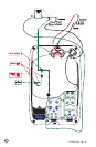
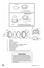
The plumbing on the spa shell is labeled by the factory in the following
manner:
Pump 1 Suction: 2” line that connects the spa lter and bottom drain as-
sembly to the front of pump 1.
Pump 1 Return: 2” line that connects the top of pump 1, through the
equipment lter and heater back to selected jets in the spa.
Pump 2 Suction: 2” line that connects the spa lter and bottom drain as-
sembly to the front of pump 2.
Pump 2 Return: 2” line that connects the top of pump 2 back to selected
jets in the spa.
Ozone Line: 1” line that connects to a 1” exible line extending off the
bottom of the equipment pack lter canister through an ozone injector (If
ozone equipped) and connected to ozone port on the spa.
Air Blower: 1 1/2” line that is plumbed out of the air blower (located on
the equipment pack) and extended up 18” above the spas water level to
prevent water ooding the air blower.