


3-3 OPERATION
A. Perform BEFORE EACH USE maintenance list
in paragraph 4-1.
B. Standard Models With Single Acting Cylinders -
Start tractor. Lower cutter decks until it is supported by
caster wheels and place hydraulic valve in “float” position.
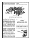
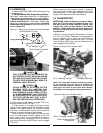
Models Equipped With Double Acting Hydraulic
Cylinder Conversion Kit - Start tractor. Lower cutter
decks until it is supported by caster wheels and hydraulic
cylinders are fully extended to allow mechanical float to
operate. (Figure 3-2)
C. With tractor at idle speed, engage PTO drive.
Advance throttle to 540 PTO rpm.
D. Place tractor in low gear and begin cutting.
Tractor forward speed should be controlled by gear
selection, not engine speed. For maximum cutting
efficiency, forward speed should allow mower to
maintain a constant maximum blade speed.
If tractor engine or cutter stalls, do not slip tractor
clutch to allow engine to retain speed as this will
exert undue strain on the implement drivetrain.
When stalling occurs, disengage PTO drive, move to
a cut area, set tractor throttle to idle, then re-engage
PTO drive.
DANGER
STAY CLEAR OF ROTATING DRIVELINE. DO
NOT OPERATE WITHOUT DRIVELINE SHIELDS
IN PLACE AND IN GOOD CONDITION. FAILURE
TO HEED THESE WARNINGS MAY RESULT IN
PERSONAL INJURY OR DEATH.
DANGER
STAND CLEAR OF ROTATING CUTTER
BLADES UNTIL ALL MOTION HAS
STOPPED. TO AVOID ACCIDENTAL FALL
AND POSSIBLE INJURY FROM CUTTER,
IT IS RECOMMENDED THAT TRACTOR
BE EQUIPPED WITH ROLLOVER PRO-
TECTIVE SYSTEM AND THAT A SEAT
BELT BE USED FOR ALL OPERATIONS
LUG SPACING
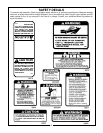
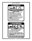
Figure 3-2 Make Sure Cylinders Are Fully Extended
To Allow Decks To Float
Wing CylinderLug Spacing
Rear Cylinder Lug Space
When mowing across slopes, yawing or skewing
may occur as the mower slips sideways which may
cause streaking. In this case, mowing up and down
slopes should be done to eliminate skewing.
3-4 TRANSPORTING
IMPORTANT- Before folding for transport, disen-
gage the PTO and wait for blades to stop. Pull
the latch chain to allow complete folding, then
release the chain to lock decks in the raised
position. These locks also serve the purpose of
limiting the upward flex of the cutter decks dur-
ing operation.
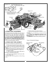
Install pins into the transport lock positions. (Figures
3-3, 3-4, & 3-5) When implement is transported on
road or highway, day or night, use tractor flashing
warning lights unless prohibited by law. The slow
moving vehicle (SMV) sign must be visible from the
rear by approaching vehicles.
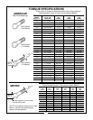
Figure 3-3 Center Unit Transport Latch
Pin In “Working” Position Transport Lock Hole
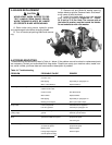
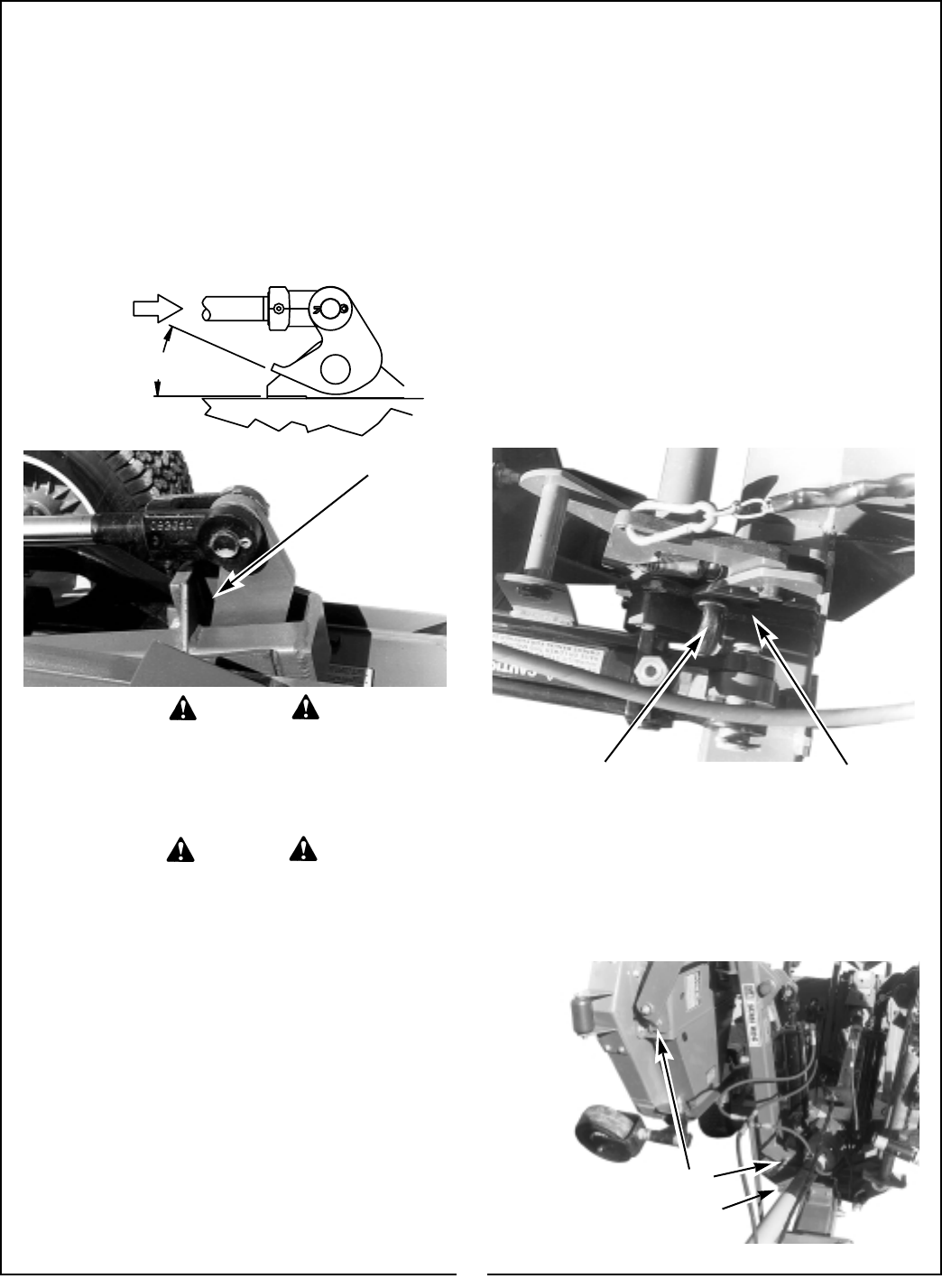
Figure 3-4 Wing Unit Transport Latch
Pins In Transport Positions
Holes For Storing Pins
During Work
9
NOTE: The mower deck transport locking pins provid-
ed on the wing sections (Figure 3-4) MUST be
removed BEFORE operation. Failure to remove these
locking pins will result in front caster wheel damage,
turf damage, and unacceptable mowing performance