


4-3 BLADE REPLACEMENT
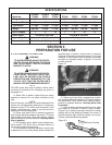
Tiller blades should be replaced when they have
approximately 1/4” of wear left on tip of
blade.(Figure 4-2) To replace blades, remove bolts
securing blade. Install new blade in its place. Blade
must be a right or left corresponding to the blade
removed. Tighten blade bolts to 118 ft. lbs. Use
only genuine Bush Hog replacement parts.
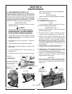
The RTN, RTNR and RTH are designed to accomo-
date up to 6 blades per flange if desired.
4-4 SLIP CLUTCH OPERATIONAL
CHECK
(IMPORTANT: Also refer to page 17)
After tiller has been stored for 30 days or more,
perform the following operational check:
A. Loosen eight nuts retaining clutch springs
exactly one full turn.
B. With tiller blades firmly on ground and tractor
at idle speed, engage tractor PTO drive for 2-3 sec-
onds. Clutch should slip without turning blades. If
clutch does not slip, contact your authorized Bush
Hog dealer.
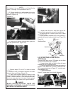
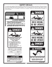
C. Retighten nuts to within 1/64” of original position.
Initial spring length is 1-3/32” (27.6mm). (Figure 4-3)
WARNING
THE TILLER CAN FALL FROM
HYDRAULIC SYSTEM FAILURE. TO
AVOID SERIOUS INJURY OR DEATH,
SECURELY SUPPORT TILLER BEFORE
WORKING UNDERNEATH.
CAUTION
FAILURE TO RETIGHTEN SPRING NUTS
TO ORIGINAL POSITION MAY CAUSE
DAMAGE TO TILLER AND/OR TRACTOR
DUE TO IMPROPER SLIP CLUTCH
TORQUE SETTING.
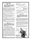
Figure 4-2 Blade Wear
1/4”
Figure 4-3
Clutch Spring Length
1-3/32”
(27.6mm)
4-5 SLIP CLUTCH ADJUSTMENT
(IMPORTANT: Also refer to page 17)
The slip clutch is factory preset to the correct torque
for protecting implement and tractor. Periodic
adjustment is recommended; refer to Section 4-4.
Should adjustment be needed, first check to be sure
all spring lengths are within 1/64” of being the same.
Initial spring length is 1-3/32” (27.6mm) shown in
Figure 4-3. If necessary, loosen nut on any spring
that is unequal. Adjust all eight spring retaining nuts
2/3 of a turn (2 flats on a nut) and check clutch slip-
page. If further adjustment is necessary, do so in 1/3
turn increments or consult your Bush Hog dealer.
Adjust only to provide sufficient torque to prevent slip-
page under normal conditions. When rocks, roots,
etc. are present, occasional slippage is normal for dri-
vetrain protection.
11
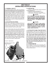
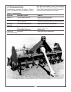
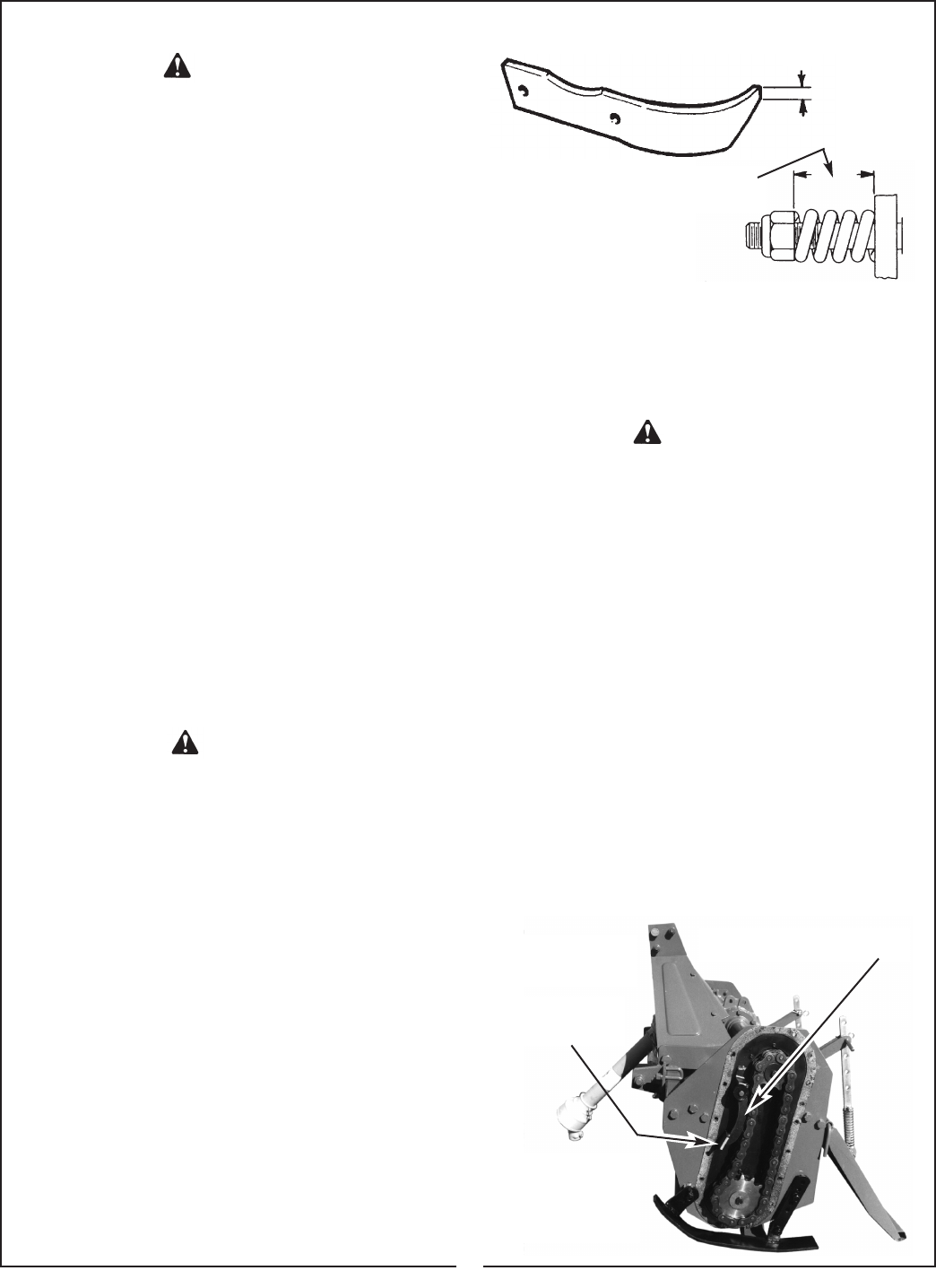
4-6 RTN CHAIN ADJUSTMENT (Figure 4-4)
A. Turn tractor off and set parking brake before
making chain adjustment.
B. Block up tiller by placing wooded block under-
neath the skids.
C. The drive chain on the Model RTN, RTNR tiller is
preset with the correct chain tension when it leaves
the factory. After an extended period of use the
chain will wear and it will be necessary to make
adjustment to the chain through the chain adjusting
bolt located on the outside of the chain case.
D. Measure the initial length of the chain tension
fastener before beginning. Rotate the bolt clockwise
to tighten the chain tension bolt to remove excess
motion of the chain. Only small increments of bolt
turns should be made, then listen for the amount of
lost motion in the chain. To much chain tension and
the rotor will be difficult to rotate.
DO NOT OVERTIGHTEN THE CHAIN TENSIONER.
PREMATURE FAILURE CAN OCCUR TO THE
CHAIN OR BEARING IF OVERTIGHTENED.
WARNING
THE TILLER CAN FALL FROM
HYDRAULIC SYSTEM FAILURE. TO AVOID
SERIOUS INJURY OR DEATH, SECURELY
SUPPORT TILLER BEFORE WORKING
UNDERNEATH
RTN Chain Tensioner Bar
Adjusting Bolt
Bears On This Pad
Figure 4-4
Chain Adjustment
NOTE:
RTNR Tensioner Bar
And Adjusting Bolt Are
Located On Opposite
Side Of Chain Case