


NOTE
If driveline is the correct length, omit the following
steps “G” through “J” and proceed to step “K”.
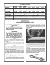
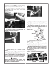
G. Clamp driveline in a well padded vice to pre-
vent damage to the shield. Cut off shield where
marked. (Figure 2-3)
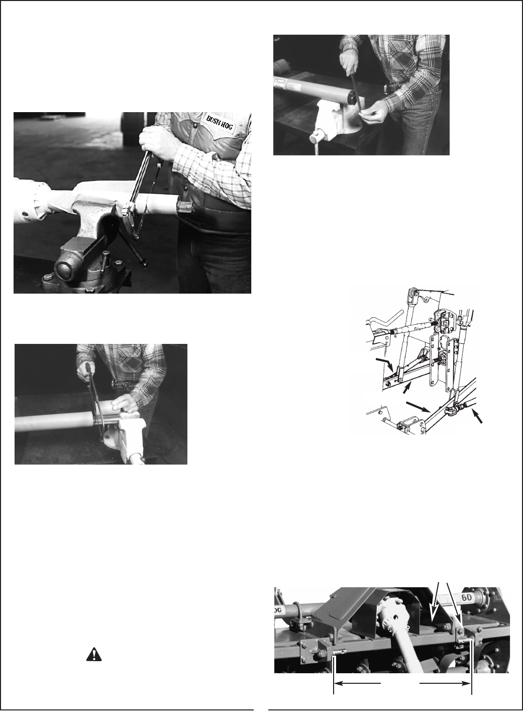
H. Using cut off section of shield as a guide, cut
shaft the same amount. (Figure 2-4)
Figure 2-4
I. Repeat steps “G” and “H” to other driveline
section.
J. Deburr ends of driveline sections and clean
away all chips and fillings. (Figure 2-5)
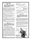
K. Apply multi-purpose grease to inside of outer
(female) driveline section. Assemble driveline and
install on tractor and tiller. Pull on each driveline sec-
tion to be sure yokes lock into place. Make certaqin
driveline shielding is in place and in good condition.
Figure 2-3
Figure 2-5
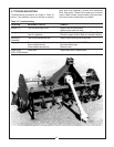
DANGER
L. Adjust lower lift arm to level tiller right to left.
Refer to tractor operator’s manual for instructions.
M. Adjust top link of tractor 3-point hitch to level
tiller front to rear.
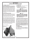
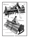
N. Set up tractor stabilizer bars, sway blocks, or
equivalent to prevent implement side sway. (Figure 2-6)
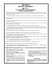
2-2 OFFSETTING 3-POINT HITCH
(RTN Series)
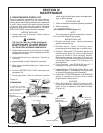
The lower hitch pins on the RTN series can be offset
up to 6 inches to either side as follows:
A. Loosen clamp bolts on hitch pin that will move
outward and slide to desired position.
B. Remove opposite hitch pin bracket and replace it
between clutch shield and “A” frame. A distance of 26-
7/8” , measured as shown in Figure 2-7, must be main-
tained between pins.
C. Tighten clamp bolts.
Figure 2-7 Lower Hitch Pins - May Be Relocated
MAKE CERTAIN DRIVELINE YOKES ARE
SECURELY FASTENED. FAILURE TO DO SO
MAY RESULT IN SERIOUS INJURY.
Figure 2-6
26-7/8”
Stabilizer
Stabilizer
Stabilizer Bars
Lift Arms
8